

Product Specification
Page 1
Intel® Desktop Boards D925XECV2/D925XEBC2 Technical Product Specification October 2004 Order Number: C90152-001 The Intel® Desktop Boards D925XECV2/D925XEBC2 may contain design defects or errors known as errata that may cause the product to deviate from published specifications. Current characterized errata are documented in the Intel Desktop Boards D925XECV2/D925XEBC2 Specification Update.
Intel® Desktop Boards D925XECV2/D925XEBC2 Technical Product Specification October 2004 Order Number: C90152-001 The Intel® Desktop Boards D925XECV2/D925XEBC2 may contain design defects or errors known as errata that may cause the product to deviate from published specifications. Current characterized errata are documented in the Intel Desktop Boards D925XECV2/D925XEBC2 Specification Update.

Product Specification
Page 2
... ordering number and are referenced in the Intel Desktop Boards D925XECV2/D925XEBC2 Specification Update before placing your distributor to only standard Intel® Desktop Boards D925XECV2 and D925XEBC2 with BIOS identifier CV92510A.86A. Intel® desktop boards may contain design defects or errors known... DOCUMENT IS PROVIDED IN CONNECTION WITH INTEL® PRODUCTS. Contact your local Intel sales office or your product order. Revision History Revision -001 Revision History First release of the Intel® Desktop Boards D925XECV2/D925XEBC2 Technical Product Specification Date ...
... ordering number and are referenced in the Intel Desktop Boards D925XECV2/D925XEBC2 Specification Update before placing your distributor to only standard Intel® Desktop Boards D925XECV2 and D925XEBC2 with BIOS identifier CV92510A.86A. Intel® desktop boards may contain design defects or errors known... DOCUMENT IS PROVIDED IN CONNECTION WITH INTEL® PRODUCTS. Contact your local Intel sales office or your product order. Revision History Revision -001 Revision History First release of the Intel® Desktop Boards D925XECV2/D925XEBC2 Technical Product Specification Date ...
Product Specification
Page 3
...detailed, technical information about the conventions used on the Desktop Boards D925XECV2 and D925XEBC2 A map of the resources of the Desktop Boards The features supported by the BIOS Setup program A ...description of the BIOS error messages, beep codes, and POST codes Typographical Conventions This section contains information about the Desktop Boards D925XECV2 and D925XEBC2 and their components to the vendors, system integrators, and other engineers and technicians who need this level of these Intel® Desktop Boards...
...detailed, technical information about the conventions used on the Desktop Boards D925XECV2 and D925XEBC2 A map of the resources of the Desktop Boards The features supported by the BIOS Setup program A ...description of the BIOS error messages, beep codes, and POST codes Typographical Conventions This section contains information about the Desktop Boards D925XECV2 and D925XEBC2 and their components to the vendors, system integrators, and other engineers and technicians who need this level of these Intel® Desktop Boards...
Product Specification
Page 4
... the instance of their respective owners. iv It is a connector, located at that general location. Voltages are the property of the particular part at 5J. Intel Desktop Boards D925XECV2/D925XEBC2 Technical Product Specification WARNING Warnings indicate conditions, which if not observed, can cause personal injury. Volts. Gigabyte (1,073,741,824 bytes) Gigabytes per...
... the instance of their respective owners. iv It is a connector, located at that general location. Voltages are the property of the particular part at 5J. Intel Desktop Boards D925XECV2/D925XEBC2 Technical Product Specification WARNING Warnings indicate conditions, which if not observed, can cause personal injury. Volts. Gigabyte (1,073,741,824 bytes) Gigabytes per...
Product Specification
Page 6
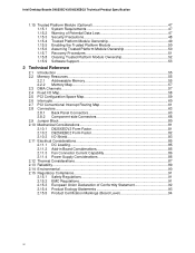
Intel Desktop Boards D925XECV2/D925XEBC2 Technical Product Specification 1.15 Trusted Platform Module (Optional 47 1.15.1 System Requirements 47 1.15.2 Warning of Potential Data Loss 47 1.15.3 Security Precautions ... 81 2.10.1 D925XECV2 Form Factor 81 2.10.2 D925XEBC2 Form Factor 82 2.10.3 I/O Shield...83 2.11 Electrical Considerations 85 2.11.1 DC Loading...85 2.11.2 Add-in Board Considerations 85 2.11.3 Fan Connector Current Capability 86 2.11.4 Power Supply Considerations 86 2.12 Thermal Considerations 87 2.13 Reliability...89 2.14 Environmental ...90 2.15 Regulatory...
Intel Desktop Boards D925XECV2/D925XEBC2 Technical Product Specification 1.15 Trusted Platform Module (Optional 47 1.15.1 System Requirements 47 1.15.2 Warning of Potential Data Loss 47 1.15.3 Security Precautions ... 81 2.10.1 D925XECV2 Form Factor 81 2.10.2 D925XEBC2 Form Factor 82 2.10.3 I/O Shield...83 2.11 Electrical Considerations 85 2.11.1 DC Loading...85 2.11.2 Add-in Board Considerations 85 2.11.3 Fan Connector Current Capability 86 2.11.4 Power Supply Considerations 86 2.12 Thermal Considerations 87 2.13 Reliability...89 2.14 Environmental ...90 2.15 Regulatory...

Product Specification
Page 7
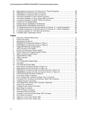
...Systems with Four DIMMs 23 8. Block Diagram...18 4. Dual Channel (Interleaved) Mode Configuration with Intel® Rapid BIOS Boot 100 3.8.1 Peripheral Selection and Configuration 100 3.8.2 Intel Rapid BIOS Boot 100 3.9 BIOS Security Features 101 4 Error Messages and Beep Codes 4.1 ... Figures 1. Front/Back Panel Audio Connector Options for D925XECV2 Board 38 16. Thermal Monitoring for D925XEBC2 Board 39 17. Memory Channel and DIMM Configuration 21 5. LAN Connector LED Locations 35 15. Desktop Board D925XECV2 Components 14 2. Contents 3 Overview of the Standby ...
...Systems with Four DIMMs 23 8. Block Diagram...18 4. Dual Channel (Interleaved) Mode Configuration with Intel® Rapid BIOS Boot 100 3.8.1 Peripheral Selection and Configuration 100 3.8.2 Intel Rapid BIOS Boot 100 3.9 BIOS Security Features 101 4 Error Messages and Beep Codes 4.1 ... Figures 1. Front/Back Panel Audio Connector Options for D925XECV2 Board 38 16. Thermal Monitoring for D925XEBC2 Board 39 17. Memory Channel and DIMM Configuration 21 5. LAN Connector LED Locations 35 15. Desktop Board D925XECV2 Components 14 2. Contents 3 Overview of the Standby ...
Product Specification
Page 8
...-side Connectors 68 22. DMA Channels ...57 13. Connection Diagram for a Two-Color Power LED 77 viii Desktop Board D925XECV2 Dimensions 81 28. Power States and Targeted System Power 42 10. PCI Configuration Space Map 59 15. Serial ATA Connectors... 17. D925XEBC2 Components Shown in Figure 21 69 20. Manufacturing Options 13 4. Back Panel Connectors for Boards with the 8-Channel (7.1) Audio Subsystem 83 30. SCSI Hard Drive Activity LED Connector (Optional 73 27. Intel Desktop Boards D925XECV2/D925XEBC2 Technical Product Specification 20. Feature Summary ...12 3.
...-side Connectors 68 22. DMA Channels ...57 13. Connection Diagram for a Two-Color Power LED 77 viii Desktop Board D925XECV2 Dimensions 81 28. Power States and Targeted System Power 42 10. PCI Configuration Space Map 59 15. Serial ATA Connectors... 17. D925XEBC2 Components Shown in Figure 21 69 20. Manufacturing Options 13 4. Back Panel Connectors for Boards with the 8-Channel (7.1) Audio Subsystem 83 30. SCSI Hard Drive Activity LED Connector (Optional 73 27. Intel Desktop Boards D925XECV2/D925XEBC2 Technical Product Specification 20. Feature Summary ...12 3.
Product Specification
Page 9
.... BIOS Error Messages 103 49. Runtime Code Uncompressed in F000 Shadow RAM 106 52. Product Certification Markings 94 44. Uncompressed INIT Code Checkpoints 105 50. Desktop Board D925XECV2/D925XEBC2 Environmental Specifications 90 41. Bus Initialization Checkpoints 109 53. Upper Nibble High Byte Functions 109 54. Lower Nibble High Byte Functions 110 55...
.... BIOS Error Messages 103 49. Runtime Code Uncompressed in F000 Shadow RAM 106 52. Product Certification Markings 94 44. Uncompressed INIT Code Checkpoints 105 50. Desktop Board D925XECV2/D925XEBC2 Environmental Specifications 90 41. Bus Initialization Checkpoints 109 53. Upper Nibble High Byte Functions 109 54. Lower Nibble High Byte Functions 110 55...
Product Specification
Page 11
... bus previously referred to as PCI is now called PCI Conventional. 1.2 Board Differences This TPS describes these Intel Desktop Boards: D925XECV2 and D925XEBC2. 1 Product Description What This Chapter Contains 1.1 PCI Bus Terminology Change 11 1.2 Board Differences ...11 1.3 Overview ...12 1.4 Online Support ...19 1.5 Processor ... 1.14 Power Management ...40 1.1 PCI Bus Terminology Change Previous generations of Intel® Desktop Boards used an add-in card connector referred to as PCI. Table 1. Summary of Board Differences D925XECV2 • ATX Form Factor (10.20 inches by 9.60 inches...
... bus previously referred to as PCI is now called PCI Conventional. 1.2 Board Differences This TPS describes these Intel Desktop Boards: D925XECV2 and D925XEBC2. 1 Product Description What This Chapter Contains 1.1 PCI Bus Terminology Change 11 1.2 Board Differences ...11 1.3 Overview ...12 1.4 Online Support ...19 1.5 Processor ... 1.14 Power Management ...40 1.1 PCI Bus Terminology Change Previous generations of Intel® Desktop Boards used an add-in card connector referred to as PCI. Table 1. Summary of Board Differences D925XECV2 • ATX Form Factor (10.20 inches by 9.60 inches...

Product Specification
Page 12
...-66/100 support • One diskette drive interface • PS/2* keyboard and mouse ports • Intel/AMI BIOS (resident in this document show only the Desktop Board D925XECV2. Intel Desktop Boards D925XECV2/D925XEBC2 Technical Product Specification NOTE Most of the illustrations in the 8 Mbit FWH) • Support for...-232, front panel, PS/2 devices, and USB ports continued 12 When there are significant differences, illustrations of both boards are provided. 1.3 Overview 1.3.1 Feature Summary Table 2 summarizes the major features of the Desktop Boards D925XECV2 and D925XEBC2.
...-66/100 support • One diskette drive interface • PS/2* keyboard and mouse ports • Intel/AMI BIOS (resident in this document show only the Desktop Board D925XECV2. Intel Desktop Boards D925XECV2/D925XEBC2 Technical Product Specification NOTE Most of the illustrations in the 8 Mbit FWH) • Support for...-232, front panel, PS/2 devices, and USB ports continued 12 When there are significant differences, illustrations of both boards are provided. 1.3 Overview 1.3.1 Feature Summary Table 2 summarizes the major features of the Desktop Boards D925XECV2 and D925XEBC2.
Product Specification
Page 13
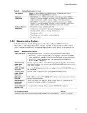
... fan activity • Fan speed control 1.3.2 Manufacturing Options Table 3 describes the manufacturing options on the Desktop Boards D925XECV2 and D925XEBC2. Please contact your Intel representative to determine which manufacturing options are available to Available configurations for the Desktop Boards D925XECV2 and D925XEBC2 Section 1.4, page 19 13 Product Description Table 2. Manufacturing Options Audio Subsystem Alternate (ALT...
... fan activity • Fan speed control 1.3.2 Manufacturing Options Table 3 describes the manufacturing options on the Desktop Boards D925XECV2 and D925XEBC2. Please contact your Intel representative to determine which manufacturing options are available to Available configurations for the Desktop Boards D925XECV2 and D925XEBC2 Section 1.4, page 19 13 Product Description Table 2. Manufacturing Options Audio Subsystem Alternate (ALT...
Product Specification
Page 14
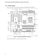
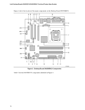
OM16676 14 Desktop Board D925XECV2 Components Table 4 lists the D925XECV2 components identified in Figure 1. A B CD E FG H I J MM K L M LL KK JJ II N O HH P GG Q FF EE DD BB Z X CC AA Y W V U T SR Figure 1. Intel Desktop Boards D925XECV2/D925XEBC2 Technical Product Specification 1.3.3 Board Layouts Figure 1 shows the location of the major components on the Desktop Board D925XECV2.
OM16676 14 Desktop Board D925XECV2 Components Table 4 lists the D925XECV2 components identified in Figure 1. A B CD E FG H I J MM K L M LL KK JJ II N O HH P GG Q FF EE DD BB Z X CC AA Y W V U T SR Figure 1. Intel Desktop Boards D925XECV2/D925XEBC2 Technical Product Specification 1.3.3 Board Layouts Figure 1 shows the location of the major components on the Desktop Board D925XECV2.
Product Specification
Page 16
Desktop Board D925XEBC2 Components Table 5 lists the D925XECV2 components identified in Figure 2. K L M N OM16686 16 A B CD E F G H I HH GG FF J EE DD CC BB AA Z Y WU X V TS R Q PO Figure 2. Intel Desktop Boards D925XECV2/D925XEBC2 Technical Product Specification Figure 2 shows the location of the major components on the Desktop Board D925XEBC2.
Desktop Board D925XEBC2 Components Table 5 lists the D925XECV2 components identified in Figure 2. K L M N OM16686 16 A B CD E F G H I HH GG FF J EE DD CC BB AA Z Y WU X V TS R Q PO Figure 2. Intel Desktop Boards D925XECV2/D925XEBC2 Technical Product Specification Figure 2 shows the location of the major components on the Desktop Board D925XEBC2.
Product Specification
Page 18
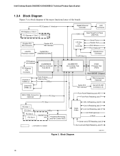
...IDE Connector Parallel ATA IDE Interface LGA775 Processor Socket System Bus (1066/800/533 MHz) PCI Express x16 Interface PCI Express x16 Connector Intel 82925XE Memory Controller Hub (MCH) Channel A DIMMs (2) Channel B DIMMs (2) Dual-Channel Memory Bus SMBus DMI Interconnect Gigabit Ethernet ...CD-ROM (optional) S/PDIF Center and LFE/Retasking Jack G Surround Left-Right/Retasking Jack H Figure 3. Block Diagram OM17471 18 Intel Desktop Boards D925XECV2/D925XEBC2 Technical Product Specification 1.3.4 Block Diagram Figure 3 is a block diagram of the major functional areas of the...
...IDE Connector Parallel ATA IDE Interface LGA775 Processor Socket System Bus (1066/800/533 MHz) PCI Express x16 Interface PCI Express x16 Connector Intel 82925XE Memory Controller Hub (MCH) Channel A DIMMs (2) Channel B DIMMs (2) Dual-Channel Memory Bus SMBus DMI Interconnect Gigabit Ethernet ...CD-ROM (optional) S/PDIF Center and LFE/Retasking Jack G Surround Left-Right/Retasking Jack H Figure 3. Block Diagram OM17471 18 Intel Desktop Boards D925XECV2/D925XEBC2 Technical Product Specification 1.3.4 Block Diagram Figure 3 is a block diagram of the major functional areas of the...
Product Specification
Page 19
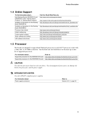
... of supported processors. See the Intel web site listed below for the Desktop Board D925XEBC2 Processor data sheets ICH6-R addressing Custom splash screens Audio software and utilities LAN software and drivers Visit this World Wide Web site: http://www.intel.com/design/motherbd http://support.intel.com/support/motherboards/desktop http://developer.intel.com/design/motherbd/cv2/cv2_available...
... of supported processors. See the Intel web site listed below for the Desktop Board D925XEBC2 Processor data sheets ICH6-R addressing Custom splash screens Audio software and utilities LAN software and drivers Visit this World Wide Web site: http://www.intel.com/design/motherbd http://support.intel.com/support/motherboards/desktop http://developer.intel.com/design/motherbd/cv2/cv2_available...
Product Specification
Page 20
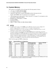
... To be fully compliant with x16 organization are not supported. • 4 GB maximum total system memory. Table 6. Intel Desktop Boards D925XECV2/D925XEBC2 Technical Product Specification 1.6 System Memory The boards have four DIMM sockets and support the following memory features: • 1.8 V and 1.9 V DDR2 SDRAM DIMMs &#...-sided or double-sided DIMMs with the following restriction: Double-sided DIMMS with all applicable DDR SDRAM memory specifications, the board should be impacted or the DIMMs may not function under the determined frequency. If non-SPD memory is installed, the ...
... To be fully compliant with x16 organization are not supported. • 4 GB maximum total system memory. Table 6. Intel Desktop Boards D925XECV2/D925XEBC2 Technical Product Specification 1.6 System Memory The boards have four DIMM sockets and support the following memory features: • 1.8 V and 1.9 V DDR2 SDRAM DIMMs &#...-sided or double-sided DIMMs with the following restriction: Double-sided DIMMS with all applicable DDR SDRAM memory specifications, the board should be impacted or the DIMMs may not function under the determined frequency. If non-SPD memory is installed, the ...
Product Specification
Page 22
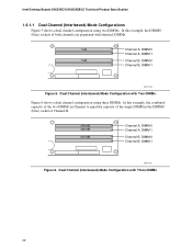
Dual Channel (Interleaved) Mode Configuration with identical DIMMs. 1 GB 1 GB Channel A, DIMM 0 Channel A, DIMM 1 Channel B, DIMM 0 Channel B, DIMM 1 OM17123 Figure 5. Intel Desktop Boards D925XECV2/D925XEBC2 Technical Product Specification 1.6.1.1 Dual Channel (Interleaved) Mode Configurations Figure 5 shows a dual channel configuration using two DIMMs. In this example, the DIMM0 (blue) sockets ...
Dual Channel (Interleaved) Mode Configuration with identical DIMMs. 1 GB 1 GB Channel A, DIMM 0 Channel A, DIMM 1 Channel B, DIMM 0 Channel B, DIMM 1 OM17123 Figure 5. Intel Desktop Boards D925XECV2/D925XEBC2 Technical Product Specification 1.6.1.1 Dual Channel (Interleaved) Mode Configurations Figure 5 shows a dual channel configuration using two DIMMs. In this example, the DIMM0 (blue) sockets ...
Product Specification
Page 24
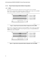
... this example, only the DIMM0 (blue) socket of Channel B. 256 MB 512 MB 512 MB Channel A, DIMM 0 Channel A, DIMM 1 Channel B, DIMM 0 Channel B, DIMM 1 OM17126 Figure 9. Intel Desktop Boards D925XECV2/D925XEBC2 Technical Product Specification 1.6.1.2 Single Channel (Asymmetric) Mode Configurations NOTE Dual channel (Interleaved) mode configurations provide the highest memory throughput.
... this example, only the DIMM0 (blue) socket of Channel B. 256 MB 512 MB 512 MB Channel A, DIMM 0 Channel A, DIMM 1 Channel B, DIMM 0 Channel B, DIMM 1 OM17126 Figure 9. Intel Desktop Boards D925XECV2/D925XEBC2 Technical Product Specification 1.6.1.2 Single Channel (Asymmetric) Mode Configurations NOTE Dual channel (Interleaved) mode configurations provide the highest memory throughput.

Product Specification
Page 25
...information about The location of the USB connectors on the back panel The location of the front panel USB connectors on the Desktop Board D925XECV2 The location of the BIOS. The ICH6-R provides the USB controller for full-speed devices. The port arrangement is ...DMI) interconnect • Intel 82801FR I /O paths. Product Description 1.7 Intel® 925XE Chipset The Intel 925XE chipset consists of the following modes: 25 For information about The Intel 925XE chipset Resources used by the chipset Refer to http://developer.intel.com/ Chapter 2 1.7.1 USB The boards support up to the...
...information about The location of the USB connectors on the back panel The location of the front panel USB connectors on the Desktop Board D925XECV2 The location of the BIOS. The ICH6-R provides the USB controller for full-speed devices. The port arrangement is ...DMI) interconnect • Intel 82801FR I /O paths. Product Description 1.7 Intel® 925XE Chipset The Intel 925XE chipset consists of the following modes: 25 For information about The Intel 925XE chipset Resources used by the chipset Refer to http://developer.intel.com/ Chapter 2 1.7.1 USB The boards support up to the...
Product Specification
Page 26
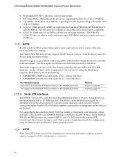
...ARMD-HDD (ATAPI removable media device - A point-to-point interface is used . Native mode is used for a maximum of four Serial ATA devices. Intel Desktop Boards D925XECV2/D925XEBC2 Technical Product Specification • Programmed I /O and IRQ resources are faster timings and require a specialized cable to the BIOS. The ICH6-R's ATA-...legacy and native modes. hard disk drive) For information about The location of the Parallel ATA IDE connector on the D925XECV2 board The location of up to 88 MB/sec. ATA-66 protocol is device driver compatible. • ATA-100: DMA protocol on ...
...ARMD-HDD (ATAPI removable media device - A point-to-point interface is used . Native mode is used for a maximum of four Serial ATA devices. Intel Desktop Boards D925XECV2/D925XEBC2 Technical Product Specification • Programmed I /O and IRQ resources are faster timings and require a specialized cable to the BIOS. The ICH6-R's ATA-...legacy and native modes. hard disk drive) For information about The location of the Parallel ATA IDE connector on the D925XECV2 board The location of up to 88 MB/sec. ATA-66 protocol is device driver compatible. • ATA-100: DMA protocol on ...


