
Product Specification
Page 9
I/O Map ...58 14. Back Panel Connectors Shown in F000 Shadow RAM 106 52. Auxiliary Power Output Connector 73 29. Alternate Power Connector 75 32. Front Panel Connector 76 34. DC Loading Characteristics 85 38. BIOS Setup ... Fan Connectors 72 24. Processor Fan Connector and Auxiliary Rear Fan Connector 72 25. Chassis Intrusion Connector 73 26. Fan Connector Current Capability 86 39. Desktop Boards D925XCV/D925XBC Environmental Specifications 90 41. BIOS Setup Program Function Keys 96 46. PCI Interrupt Routing Map 62 17. States for a Two-Color Power LED...
I/O Map ...58 14. Back Panel Connectors Shown in F000 Shadow RAM 106 52. Auxiliary Power Output Connector 73 29. Alternate Power Connector 75 32. Front Panel Connector 76 34. DC Loading Characteristics 85 38. BIOS Setup ... Fan Connectors 72 24. Processor Fan Connector and Auxiliary Rear Fan Connector 72 25. Chassis Intrusion Connector 73 26. Fan Connector Current Capability 86 39. Desktop Boards D925XCV/D925XBC Environmental Specifications 90 41. BIOS Setup Program Function Keys 96 46. PCI Interrupt Routing Map 62 17. States for a Two-Color Power LED...

Product Specification
Page 12
...• Suspend to RAM support • Wake on PCI, RS-232, front panel, PS/2 devices, and USB ports continued 12 Intel Desktop Boards D925XCV/D925XBC Technical Product Specification ✏ NOTE Most of : • Intel® 82925X Memory Controller Hub (MCH) • Intel® 82801FR I/O ... • PS/2* keyboard and mouse ports • Intel/AMI BIOS (resident in this document show only the Desktop Board D925XCV. When there are significant differences between the two Desktop Boards, illustrations of both boards are provided. 1.3 Overview 1.3.1 Feature Summary Table 2 summarizes...
...• Suspend to RAM support • Wake on PCI, RS-232, front panel, PS/2 devices, and USB ports continued 12 Intel Desktop Boards D925XCV/D925XBC Technical Product Specification ✏ NOTE Most of : • Intel® 82925X Memory Controller Hub (MCH) • Intel® 82801FR I/O ... • PS/2* keyboard and mouse ports • Intel/AMI BIOS (resident in this document show only the Desktop Board D925XCV. When there are significant differences between the two Desktop Boards, illustrations of both boards are provided. 1.3 Overview 1.3.1 Feature Summary Table 2 summarizes...

Product Specification
Page 28
...interface includes the following PCI Express connectors: • One PCI Express x16 connector. When the computer is not plugged into CMOS RAM at up to 8 GBytes/sec. The PCI Express interface supports the PCI Conventional bus configuration mechanism so that can be off function... battery has an estimated life of the battery. one PCI Express x1 connector on the D925XCV board; The clock is controlled from the power supply extends the life of three years. Intel Desktop Boards D925XCV/D925XBC Technical Product Specification 1.7.3 Real-Time Clock, CMOS SRAM, and Battery A coin-cell...
...interface includes the following PCI Express connectors: • One PCI Express x16 connector. When the computer is not plugged into CMOS RAM at up to 8 GBytes/sec. The PCI Express interface supports the PCI Conventional bus configuration mechanism so that can be off function... battery has an estimated life of the battery. one PCI Express x1 connector on the D925XCV board; The clock is controlled from the power supply extends the life of three years. Intel Desktop Boards D925XCV/D925XBC Technical Product Specification 1.7.3 Real-Time Clock, CMOS SRAM, and Battery A coin-cell...
Product Specification
Page 42
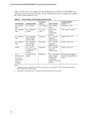
Intel Desktop Boards D925XCV/D925XBC Technical Product Specification Table 9 lists the power states supported by battery or external source. sleeping state G1 - S4 - Context saved to RAM. stop grant No power No power No power No power Device States D0 - D1, D2, D3 -...States and Targeted System Power Global States G0 - Context not saved. no power for wake-up logic, except when provided by the Desktop Boards D925XCV and D925XBC along with the associated system power targets. no power except for wake-up logic. Service can be performed safely. Sleeping...
Intel Desktop Boards D925XCV/D925XBC Technical Product Specification Table 9 lists the power states supported by battery or external source. sleeping state G1 - S4 - Context saved to RAM. stop grant No power No power No power No power Device States D0 - D1, D2, D3 -...States and Targeted System Power Global States G0 - Context not saved. no power for wake-up logic, except when provided by the Desktop Boards D925XCV and D925XBC along with the associated system power targets. no power except for wake-up logic. Service can be performed safely. Sleeping...

Product Specification
Page 45
...must be capable of Resume on Ring The operation of providing adequate +5 V standby current. Instantly Available PC technology enables the Desktop Boards D925XCV and D925XBC to enter the ACPI S3 (Suspend-to provide adequate standby current when implementing Instantly Available PC technology can be... summarized as follows: • Resumes operation from the S3 state. Failure to -RAM) sleep-state. Product Description Depending on the LAN implementation, the Desktop Boards D925XCV and D925XBC support LAN wake capabilities with Wake on PME enabled in BIOS). 45 While in ...
...must be capable of Resume on Ring The operation of providing adequate +5 V standby current. Instantly Available PC technology enables the Desktop Boards D925XCV and D925XBC to enter the ACPI S3 (Suspend-to provide adequate standby current when implementing Instantly Available PC technology can be... summarized as follows: • Resumes operation from the S3 state. Failure to -RAM) sleep-state. Product Description Depending on the LAN implementation, the Desktop Boards D925XCV and D925XBC support LAN wake capabilities with Wake on PME enabled in BIOS). 45 While in ...

Product Specification
Page 105
... code checkpoints, Table 50 describes the boot block recovery code checkpoints, and Table 51 lists the runtime code uncompressed in F000 shadow RAM. Initialize extra (Intel Recovery) Module. Error Messages and Beep Codes 4.2 Port 80h POST Codes During the POST, the BIOS generates diagnostic progress codes (...POST-codes) to 4 GB flat mode. Table 49. Copy main BIOS image to F000 shadow RAM and give control to be installed in card, ...
... code checkpoints, Table 50 describes the boot block recovery code checkpoints, and Table 51 lists the runtime code uncompressed in F000 shadow RAM. Initialize extra (Intel Recovery) Module. Error Messages and Beep Codes 4.2 Port 80h POST Codes During the POST, the BIOS generates diagnostic progress codes (...POST-codes) to 4 GB flat mode. Table 49. Copy main BIOS image to F000 shadow RAM and give control to be installed in card, ...

Product Specification
Page 106
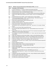
...error messages. (See Section 4.3 for details of , key during power-on. 12 To init CMOS if "Init CMOS in F000 Shadow RAM Code Description of different buses.) 2B To give control for any processing after KB controller BAT to be done next. 0F Keyboard command byte...NMI is pressed. About to check pressing of different buses.) 3A New cursor position read 8042 input port and disable Megakey GreenPC feature. Intel Desktop Boards D925XCV/D925XBC Technical Product Specification Table 51. Going to display the power-on . 05 BIOS stack set . continued 106 To look for...
...error messages. (See Section 4.3 for details of , key during power-on. 12 To init CMOS if "Init CMOS in F000 Shadow RAM Code Description of different buses.) 2B To give control for any processing after KB controller BAT to be done next. 0F Keyboard command byte...NMI is pressed. About to check pressing of different buses.) 3A New cursor position read 8042 input port and disable Megakey GreenPC feature. Intel Desktop Boards D925XCV/D925XBC Technical Product Specification Table 51. Going to display the power-on . 05 BIOS stack set . continued 106 To look for...

Product Specification
Page 107
Runtime Code Uncompressed in base memory. Going to display the first 64k memory size. Patterns written in F000 Shadow RAM (continued) Code 40 42 43 44 45 46 47 48 49 4B 4C 4D 4E 4F 50 51 52 53 54 57 58 59 60 ...
Runtime Code Uncompressed in base memory. Going to display the first 64k memory size. Patterns written in F000 Shadow RAM (continued) Code 40 42 43 44 45 46 47 48 49 4B 4C 4D 4E 4F 50 51 52 53 54 57 58 59 60 ...
Product Specification
Page 108
...any initialization before Coprocessor test. 9C Required initialization before Coprocessor is complete. AD Put CGA INT10 module (if present) in F000 Shadow RAM (continued) Code Description of POST Operation 84 Lock-key checking over . About to start . 8D Going for hard disk controller ...CMOS setup program and screen is done. AC Generate MP for memory size mismatch with CMOS. 85 Memory size check done. Intel Desktop Boards D925XCV/D925XBC Technical Product Specification Table 51. About to do programming before setup. 87 Programming before giving control to do any ...
...any initialization before Coprocessor test. 9C Required initialization before Coprocessor is complete. AD Put CGA INT10 module (if present) in F000 Shadow RAM (continued) Code Description of POST Operation 84 Lock-key checking over . About to start . 8D Going for hard disk controller ...CMOS setup program and screen is done. AC Generate MP for memory size mismatch with CMOS. 85 Memory size check done. Intel Desktop Boards D925XCV/D925XBC Technical Product Specification Table 51. About to do programming before setup. 87 Programming before giving control to do any ...

Product Specification
Page 109
... on the bus concerned. Init of POST Operation AE Uncompress SMBIOS module and init SMBIOS code and form the runtime SMBIOS image in F000 Shadow RAM (continued) Code Description of different buses optional ROMs from which routine is passed to the different bus routines. Runtime Code Uncompressed in shadow.
... on the bus concerned. Init of POST Operation AE Uncompress SMBIOS module and init SMBIOS code and form the runtime SMBIOS image in F000 Shadow RAM (continued) Code Description of different buses optional ROMs from which routine is passed to the different bus routines. Runtime Code Uncompressed in shadow.


