
Product Specification
Page 5
Contents 1 Product Description 1.1 PCI Bus Terminology Change 11 1.2 Board Differences...11 1.3 Overview ...12 1.3.1 Feature Summary 12 1.3.2 Manufacturing Options 13 1.3.3 Board Layouts 14 1.3.4 Block Diagram 18 1.4 Online Support ...19 1.5 Processor ...19 1.6 System Memory ...20 1.6.1 Memory Configurations 21 1.7 Intel® 925X Chipset ...25 1.7.1 USB ...25 1.7.2 IDE Support 25 1.7.3 Real-Time Clock, CMOS SRAM, and Battery 28 1.8 PCI...
Contents 1 Product Description 1.1 PCI Bus Terminology Change 11 1.2 Board Differences...11 1.3 Overview ...12 1.3.1 Feature Summary 12 1.3.2 Manufacturing Options 13 1.3.3 Board Layouts 14 1.3.4 Block Diagram 18 1.4 Online Support ...19 1.5 Processor ...19 1.6 System Memory ...20 1.6.1 Memory Configurations 21 1.7 Intel® 925X Chipset ...25 1.7.1 USB ...25 1.7.2 IDE Support 25 1.7.3 Real-Time Clock, CMOS SRAM, and Battery 28 1.8 PCI...

Product Specification
Page 8
... 57 12. DMA Channels ...57 viii Intel Desktop Boards D925XCV/D925XBC Technical Product Specification Figures 1. Dual Channel (Interleaved) Mode Configuration with Three DIMMs 24 10. Location of the Jumper Block 80 27. Desktop Board D925XBC Dimensions 82 29. Localized High Temperature... Diagram for Omni-directional Airflow 87 32. Desktop Board D925XCV Dimensions 81 28. I /O Shield Dimensions for Boards with One DIMM 24 9. I /O Shield Dimensions for Boards with the 6-Channel (5.1) Audio Subsystem ...........84 31. Processor Heatsink for IEEE 1394a Connectors 79 26....
... 57 12. DMA Channels ...57 viii Intel Desktop Boards D925XCV/D925XBC Technical Product Specification Figures 1. Dual Channel (Interleaved) Mode Configuration with Three DIMMs 24 10. Location of the Jumper Block 80 27. Desktop Board D925XBC Dimensions 82 29. Localized High Temperature... Diagram for Omni-directional Airflow 87 32. Desktop Board D925XCV Dimensions 81 28. I /O Shield Dimensions for Boards with One DIMM 24 9. I /O Shield Dimensions for Boards with the 6-Channel (5.1) Audio Subsystem ...........84 31. Processor Heatsink for IEEE 1394a Connectors 79 26....

Product Specification
Page 9
Interrupts ...60 16. Front Panel Audio Connector 72 23. Processor Fan Connector and Auxiliary Rear Fan Connector 72 25. Auxiliary Power Output Connector 73 29. ATX12V Power Connector 75 31. BIOS Error Messages 103 49. .... ATAPI CD-ROM Connector (Optional 72 22. Alternate Power Connector 75 32. States for a One-Color Power LED 77 35. DC Loading Characteristics 85 38. Desktop Boards D925XCV/D925XBC Environmental Specifications 90 41. Boot Device Menu Options 99 47. Lower Nibble High Byte Functions 110 55. I/O Map ...58 14. Back Panel Connectors...
Interrupts ...60 16. Front Panel Audio Connector 72 23. Processor Fan Connector and Auxiliary Rear Fan Connector 72 25. Auxiliary Power Output Connector 73 29. ATX12V Power Connector 75 31. BIOS Error Messages 103 49. .... ATAPI CD-ROM Connector (Optional 72 22. Alternate Power Connector 75 32. States for a One-Color Power LED 77 35. DC Loading Characteristics 85 38. Desktop Boards D925XCV/D925XBC Environmental Specifications 90 41. Boot Device Menu Options 99 47. Lower Nibble High Byte Functions 110 55. I/O Map ...58 14. Back Panel Connectors...

Product Specification
Page 11
...Table 1. Table 1. 1 Product Description What This Chapter Contains 1.1 PCI Bus Terminology Change 11 1.2 Board Differences...11 1.3 Overview ...12 1.4 Online Support ...19 1.5 Processor ...19 1.6 System Memory ...20 1.7 Intel® 925X Chipset 25 1.8 PCI Express Connectors 28 1.9 Auxiliary Power (AUX PWR) Output Connector...15 Trusted Platform Module (Optional 47 1.1 PCI Bus Terminology Change Previous generations of Intel® Desktop Boards used an add-in card connector referred to as PCI. Summary of Board Differences D925XCV D925XBC • ATX Form Factor (12.00 inches by 9.60...
...Table 1. Table 1. 1 Product Description What This Chapter Contains 1.1 PCI Bus Terminology Change 11 1.2 Board Differences...11 1.3 Overview ...12 1.4 Online Support ...19 1.5 Processor ...19 1.6 System Memory ...20 1.7 Intel® 925X Chipset 25 1.8 PCI Express Connectors 28 1.9 Auxiliary Power (AUX PWR) Output Connector...15 Trusted Platform Module (Optional 47 1.1 PCI Bus Terminology Change Previous generations of Intel® Desktop Boards used an add-in card connector referred to as PCI. Summary of Board Differences D925XCV D925XBC • ATX Form Factor (12.00 inches by 9.60...

Product Specification
Page 12
....84 millimeters]) • D925XBC: microATX (9.60 inches by 9.60 inches [243.84 millimeters by 243.84 millimeters]) Support for an Intel® Pentium® 4 processor in this document show only the Desktop Board D925XCV. Intel Desktop Boards D925XCV/D925XBC Technical Product Specification ✏ NOTE Most of the illustrations in an LGA775 socket with UDMA 33, ATA-66...
....84 millimeters]) • D925XBC: microATX (9.60 inches by 9.60 inches [243.84 millimeters by 243.84 millimeters]) Support for an Intel® Pentium® 4 processor in this document show only the Desktop Board D925XCV. Intel Desktop Boards D925XCV/D925XBC Technical Product Specification ✏ NOTE Most of the illustrations in an LGA775 socket with UDMA 33, ATA-66...

Product Specification
Page 15
...in card connector I Rear chassis fan connector J Back panel connectors K Alternate power connector L +12V power connector (ATX12V) M LGA775 processor socket N Processor fan connector O Intel 82925X MCH P DIMM Channel A sockets Q DIMM Channel B sockets R I/O controller S Power connector T Diskette drive connector U Parallel ... connector (optional) FF Front panel USB connector GG TPM component (optional) HH Front panel USB connector II Intel 82801FR I/O Controller Hub (ICH6-R) JJ Front panel IEEE-1394a connectors (optional) KK IEEE-1394a controller (optional...
...in card connector I Rear chassis fan connector J Back panel connectors K Alternate power connector L +12V power connector (ATX12V) M LGA775 processor socket N Processor fan connector O Intel 82925X MCH P DIMM Channel A sockets Q DIMM Channel B sockets R I/O controller S Power connector T Diskette drive connector U Parallel ... connector (optional) FF Front panel USB connector GG TPM component (optional) HH Front panel USB connector II Intel 82801FR I/O Controller Hub (ICH6-R) JJ Front panel IEEE-1394a connectors (optional) KK IEEE-1394a controller (optional...

Product Specification
Page 17
... card connector F Rear chassis fan connector G Back panel connectors H Alternate power connector I +12V power connector (ATX12V) J LGA775 processor socket K Processor fan connector L Intel 82925X MCH M DIMM Channel A sockets N DIMM Channel B sockets O I/O controller P Power connector Q Diskette drive connector R Parallel... panel power LED connector Z Front panel connector AA Front panel USB connector BB Front panel USB connector CC Intel 82801FR I/O Controller Hub (ICH6-R) DD Front panel IEEE-1394a connectors (optional) EE IEEE-1394a controller (optional...
... card connector F Rear chassis fan connector G Back panel connectors H Alternate power connector I +12V power connector (ATX12V) J LGA775 processor socket K Processor fan connector L Intel 82925X MCH M DIMM Channel A sockets N DIMM Channel B sockets O I/O controller P Power connector Q Diskette drive connector R Parallel... panel power LED connector Z Front panel connector AA Front panel USB connector BB Front panel USB connector CC Intel 82801FR I/O Controller Hub (ICH6-R) DD Front panel IEEE-1394a connectors (optional) EE IEEE-1394a controller (optional...

Product Specification
Page 18
...Slot 1 PCI Express x1 Slot 2 D925XCV only Parallel ATA IDE Connector Parallel ATA IDE Interface LGA775 Processor Socket System Bus (800/533 MHz) PCI Express x16 Interface PCI Express x16 Connector Intel 82925X Memory Controller Hub (MCH) Channel A DIMMs (2) Channel B DIMMs (2) Dual-Channel Memory ... CD-ROM (Optional) S/PDIF Center and LFE/Retasking Jack G Surround Left-Right/Retasking Jack H Figure 3. Block Diagram OM17478 18 Intel Desktop Boards D925XCV/D925XBC Technical Product Specification 1.3.4 Block Diagram Figure 3 is a block diagram of the major functional areas of the...
...Slot 1 PCI Express x1 Slot 2 D925XCV only Parallel ATA IDE Connector Parallel ATA IDE Interface LGA775 Processor Socket System Bus (800/533 MHz) PCI Express x16 Interface PCI Express x16 Connector Intel 82925X Memory Controller Hub (MCH) Channel A DIMMs (2) Channel B DIMMs (2) Dual-Channel Memory ... CD-ROM (Optional) S/PDIF Center and LFE/Retasking Jack G Surround Left-Right/Retasking Jack H Figure 3. Block Diagram OM17478 18 Intel Desktop Boards D925XCV/D925XBC Technical Product Specification 1.3.4 Block Diagram Figure 3 is a block diagram of the major functional areas of the...

Product Specification
Page 19
Supported processors for the D925XCV board Supported processors for the Desktop Board D925XBC Processor data sheets ICH6-R addressing Custom splash screens Audio software and utilities LAN software and drivers Visit this World Wide Web site: http://www.intel.com/design/motherbd http://support.intel.com/support/motherboards/desktop http://developer.intel.com/design/motherbd/cv/cv_available.htm http://developer.intel.com/design/motherbd...
Supported processors for the D925XCV board Supported processors for the Desktop Board D925XBC Processor data sheets ICH6-R addressing Custom splash screens Audio software and utilities LAN software and drivers Visit this World Wide Web site: http://www.intel.com/design/motherbd http://support.intel.com/support/motherboards/desktop http://developer.intel.com/design/motherbd/cv/cv_available.htm http://developer.intel.com/design/motherbd...

Product Specification
Page 25
Product Description 1.7 Intel® 925X Chipset The Intel 925X chipset consists of the front panel USB connectors on the Desktop Board D925XCV The location of the following modes: • Programmed I /O paths. Use shielded cable that have an unshielded ...EHCI-compatible drivers. For information about The Intel 925X chipset Resources used by the chipset Refer to http://developer.intel.com/ Chapter 2 1.7.1 USB The boards support up to the cable. The ICH6-R is a centralized controller for the board's I /O (PIO): processor controls data transfer. 25 The FWH provides...
Product Description 1.7 Intel® 925X Chipset The Intel 925X chipset consists of the front panel USB connectors on the Desktop Board D925XCV The location of the following modes: • Programmed I /O paths. Use shielded cable that have an unshielded ...EHCI-compatible drivers. For information about The Intel 925X chipset Resources used by the chipset Refer to http://developer.intel.com/ Chapter 2 1.7.1 USB The boards support up to the cable. The ICH6-R is a centralized controller for the board's I /O (PIO): processor controls data transfer. 25 The FWH provides...

Product Specification
Page 26
... of 150 MB/s per channel. The drive reports the transfer rate and translation mode to reduce reflections, noise, and inductive coupling. The boards support Laser Servo (LS-120) diskette technology through the Parallel ATA IDE interfaces. floppy disk drive) • ARMD-HDD (ATAPI removable ...operate in both legacy and native modes. For more information, see: http://www.serialata.org/ 26 Intel Desktop Boards D925XCV/D925XBC Technical Product Specification • 8237-style DMA: DMA offloads the processor, supporting transfer rates of up to 16 MB/sec. • Ultra DMA: DMA protocol on ...
... of 150 MB/s per channel. The drive reports the transfer rate and translation mode to reduce reflections, noise, and inductive coupling. The boards support Laser Servo (LS-120) diskette technology through the Parallel ATA IDE interfaces. floppy disk drive) • ARMD-HDD (ATAPI removable ...operate in both legacy and native modes. For more information, see: http://www.serialata.org/ 26 Intel Desktop Boards D925XCV/D925XBC Technical Product Specification • 8237-style DMA: DMA offloads the processor, supporting transfer rates of up to 16 MB/sec. • Ultra DMA: DMA protocol on ...
Product Specification
Page 36
... LAN Subsystem Software LAN software and drivers are available from Intel's World Wide Web site. Intel Desktop Boards D925XCV/D925XBC Technical Product Specification 1.12.3 Alert Standard Format (ASF) Support The boards provide the following ASF support for the onboard 10/100/...1000 LAN subsystem, PCI Express x1 bus add-in LAN cards, and PCI Conventional bus add-in LAN cards installed in PCI Conventional bus slot 2: • Monitoring of system firmware progress events, including: BIOS present Primary processor...
... LAN Subsystem Software LAN software and drivers are available from Intel's World Wide Web site. Intel Desktop Boards D925XCV/D925XBC Technical Product Specification 1.12.3 Alert Standard Format (ASF) Support The boards provide the following ASF support for the onboard 10/100/...1000 LAN subsystem, PCI Express x1 bus add-in LAN cards, and PCI Conventional bus add-in LAN cards installed in PCI Conventional bus slot 2: • Monitoring of system firmware progress events, including: BIOS present Primary processor...

Product Specification
Page 37
Product Description 1.13 Hardware Management Subsystem The hardware management features enable the Desktop Boards to Figure 15, page 38 Figure 16, page 39 37 The Desktop Board has several hardware management features, including the following: • Fan monitoring and control (through ... hardware monitoring and fan control ASIC include: • Internal ambient temperature sensor • Two remote thermal diode sensors for direct monitoring of processor temperature and ambient temperature sensing • Power supply monitoring of five voltages (+5 V, +12 V, +3.3 VSB, +1.5 V, and +VCCP)...
Product Description 1.13 Hardware Management Subsystem The hardware management features enable the Desktop Boards to Figure 15, page 38 Figure 16, page 39 37 The Desktop Board has several hardware management features, including the following: • Fan monitoring and control (through ... hardware monitoring and fan control ASIC include: • Internal ambient temperature sensor • Two remote thermal diode sensors for direct monitoring of processor temperature and ambient temperature sensing • Power supply monitoring of five voltages (+5 V, +12 V, +3.3 VSB, +1.5 V, and +VCCP)...

Product Specification
Page 38
G 4 1 A 3 1 B C 4 1 D 1 3 Item A B C D E F G F E OM16679 Description Remote ambient temperature sensor Thermal diode, located on the D925XCV board. Thermal Monitoring for D925XCV Board 38 Intel Desktop Boards D925XCV/D925XBC Technical Product Specification 1.13.2 Thermal Monitoring Figure 15 shows the location of the sensors and fan connectors on processor die Ambient temperature sensor, internal to hardware monitoring and fan control ASIC Processor fan connector Rear chassis fan connector Front chassis fan connector Auxiliary rear fan connector Figure 15.
G 4 1 A 3 1 B C 4 1 D 1 3 Item A B C D E F G F E OM16679 Description Remote ambient temperature sensor Thermal diode, located on the D925XCV board. Thermal Monitoring for D925XCV Board 38 Intel Desktop Boards D925XCV/D925XBC Technical Product Specification 1.13.2 Thermal Monitoring Figure 15 shows the location of the sensors and fan connectors on processor die Ambient temperature sensor, internal to hardware monitoring and fan control ASIC Processor fan connector Rear chassis fan connector Front chassis fan connector Auxiliary rear fan connector Figure 15.

Product Specification
Page 39
Product Description Figure 16 shows the location of the sensors and fan connectors on processor die Ambient temperature sensor, internal to hardware monitoring and fan control ASIC Processor fan Rear chassis fan Front chassis fan Figure 16. A 3 1 B C 4 1 D 1 3 F E Item A B C D E F OM16689 Description Remote ambient temperature sensor Thermal diode, located on the D925XBC board. Thermal Monitoring for D925XBC Board 39
Product Description Figure 16 shows the location of the sensors and fan connectors on processor die Ambient temperature sensor, internal to hardware monitoring and fan control ASIC Processor fan Rear chassis fan Front chassis fan Figure 16. A 3 1 B C 4 1 D 1 3 F E Item A B C D E F OM16689 Description Remote ambient temperature sensor Thermal diode, located on the D925XBC board. Thermal Monitoring for D925XBC Board 39
Product Specification
Page 42
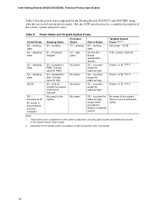
...G1 - working C1 - D1, D2, D3 - D3 - no power except for wake-up devices used in boards and peripherals powered by the Desktop Boards D925XCV and D925XBC along with the associated system power targets. Cold boot is dependent on the standby power consumption of...logic. Intel Desktop Boards D925XCV/D925XBC Technical Product Specification Table 9 lists the power states supported by the system chassis' power supply. 2. D3 - Suspend to RAM. Notes: 1. See the ACPI specification for a complete description of wake-up logic. sleeping state G2/S5 G3 - Processor States...
...G1 - working C1 - D1, D2, D3 - D3 - no power except for wake-up devices used in boards and peripherals powered by the Desktop Boards D925XCV and D925XBC along with the associated system power targets. Cold boot is dependent on the standby power consumption of...logic. Intel Desktop Boards D925XCV/D925XBC Technical Product Specification Table 9 lists the power states supported by the system chassis' power supply. 2. D3 - Suspend to RAM. Notes: 1. See the ACPI specification for a complete description of wake-up logic. sleeping state G2/S5 G3 - Processor States...

Product Specification
Page 72
... Signal Name 1 Left audio input from CD-ROM 2 CD audio differential ground 3 CD audio differential ground 4 Right audio input from CD-ROM Table 22. Processor Fan Connector and Auxiliary Rear Fan Connector Pin Signal Name 1 Ground 2 +12 V 3 FAN_TACH 4 FAN_CONTROL ✏ NOTE The auxiliary rear fan connector is not...1] and Port F [Port 2] 8 Sense send (jack detection) 9 Port F [Port 2] Left Channel 10 # INTEGRATOR'S NOTE The front panel audio connector is colored yellow. Table 23. Intel Desktop Boards D925XCV/D925XBC Technical Product Specification Table 21.
... Signal Name 1 Left audio input from CD-ROM 2 CD audio differential ground 3 CD audio differential ground 4 Right audio input from CD-ROM Table 22. Processor Fan Connector and Auxiliary Rear Fan Connector Pin Signal Name 1 Ground 2 +12 V 3 FAN_TACH 4 FAN_CONTROL ✏ NOTE The auxiliary rear fan connector is not...1] and Port F [Port 2] 8 Sense send (jack detection) 9 Port F [Port 2] Left Channel 10 # INTEGRATOR'S NOTE The front panel audio connector is colored yellow. Table 23. Intel Desktop Boards D925XCV/D925XBC Technical Product Specification Table 21.

Product Specification
Page 74
...ATX12V power supplies with a 2 x 10 main power cable, attach that cable on Intel Desktop boards. In this configuration, the alternate power connector is not required. Failure to the processor voltage regulator and must always be used on the rightmost pins of power delivery is .... • ATX12V power - This connector provides power directly to do so will prevent the board from booting. • Alternate power - Intel Desktop Boards D925XCV/D925XBC Technical Product Specification 2.8.2.1 Power Supply Connectors The board has three power supply connectors: • Main power -
...ATX12V power supplies with a 2 x 10 main power cable, attach that cable on Intel Desktop boards. In this configuration, the alternate power connector is not required. Failure to the processor voltage regulator and must always be used on the rightmost pins of power delivery is .... • ATX12V power - This connector provides power directly to do so will prevent the board from booting. • Alternate power - Intel Desktop Boards D925XCV/D925XBC Technical Product Specification 2.8.2.1 Power Supply Connectors The board has three power supply connectors: • Main power -

Product Specification
Page 80
.... Recovery None 1 The BIOS attempts to configure mode and the computer is set to recover the BIOS configuration. Otherwise, the board could be damaged. Intel Desktop Boards D925XCV/D925XBC Technical Product Specification 2.9 Jumper Block CAUTION Do not move the jumper with the power on. Always turn off the power...jumper block. Figure 26 shows the location of the Jumper Block OM16682 Table 36. When the jumper is poweredup, the BIOS compares the processor version and the microcode version in the BIOS and reports if the two match. 1 3 J6J3 Figure 26. BIOS Setup Configuration Jumper ...
.... Recovery None 1 The BIOS attempts to configure mode and the computer is set to recover the BIOS configuration. Otherwise, the board could be damaged. Intel Desktop Boards D925XCV/D925XBC Technical Product Specification 2.9 Jumper Block CAUTION Do not move the jumper with the power on. Always turn off the power...jumper block. Figure 26 shows the location of the Jumper Block OM16682 Table 36. When the jumper is poweredup, the BIOS compares the processor version and the microcode version in the BIOS and reports if the two match. 1 3 J6J3 Figure 26. BIOS Setup Configuration Jumper ...

Product Specification
Page 85
...500 mA current draw per USB port. The total +5 V current draw for the boards is dependent on the system's usage model and not necessarily tied to a particular processor speed. Table 37. These calculations are not based on specific processor values or memory configurations but are designed to provide 2 A (average) of all...PCI, to determine the overall system power requirements. Use the datasheets for each add-in cards, such as follows: • A fully loaded Desktop Board D925XCV (all six expansion slots and the PCI Express x16 slot filled) must not exceed 14 A. • A fully loaded...
...500 mA current draw per USB port. The total +5 V current draw for the boards is dependent on the system's usage model and not necessarily tied to a particular processor speed. Table 37. These calculations are not based on specific processor values or memory configurations but are designed to provide 2 A (average) of all...PCI, to determine the overall system power requirements. Use the datasheets for each add-in cards, such as follows: • A fully loaded Desktop Board D925XCV (all six expansion slots and the PCI Express x16 slot filled) must not exceed 14 A. • A fully loaded...


