
Product Guide
Page 5
... Manufacturing Options ...11 Supported Operating Systems 11 Desktop Board Components 12 Processor ...16 Main Memory ...17 Intel® 915P Express Chipset 18 Audio Subsystem ...18 Input/Output (I/O) Controller 19 LAN Subsystem (Optional 19 LAN Subsystem Software 20 RJ-45 ... Speed Control (Intel® Precision Cooling Technology 23 Suspend to RAM (Instantly Available PC Technology 23 Resume on Ring...24 Wake from USB...24 Wake from PS/2 Keyboard/Mouse 25 PME# Wakeup Support 25 Speaker...25 Battery...25 Real-Time Clock...25 2 Installing and Replacing Desktop Board Components Before You...
... Manufacturing Options ...11 Supported Operating Systems 11 Desktop Board Components 12 Processor ...16 Main Memory ...17 Intel® 915P Express Chipset 18 Audio Subsystem ...18 Input/Output (I/O) Controller 19 LAN Subsystem (Optional 19 LAN Subsystem Software 20 RJ-45 ... Speed Control (Intel® Precision Cooling Technology 23 Suspend to RAM (Instantly Available PC Technology 23 Resume on Ring...24 Wake from USB...24 Wake from PS/2 Keyboard/Mouse 25 PME# Wakeup Support 25 Speaker...25 Battery...25 Real-Time Clock...25 2 Installing and Replacing Desktop Board Components Before You...

Product Guide
Page 6
Intel Desktop Board D915PGN/D915PSY/D915PCY/D915PCM Product Guide Installing the I/O Shield ...30 Installing and Removing the Desktop Board 31 Installing and Removing a Processor 32 Installing a Processor 32 Installing the Processor Fan Heat Sink 34 Connecting the Processor Fan Heat Sink Cable 35 Removing the Processor 35 Installing and Removing Memory 36 Installing DIMMs...38 Removing DIMMs...40 Installing and Removing a PCI...
Intel Desktop Board D915PGN/D915PSY/D915PCY/D915PCM Product Guide Installing the I/O Shield ...30 Installing and Removing the Desktop Board 31 Installing and Removing a Processor 32 Installing a Processor 32 Installing the Processor Fan Heat Sink 34 Connecting the Processor Fan Heat Sink Cable 35 Removing the Processor 35 Installing and Removing Memory 36 Installing DIMMs...38 Removing DIMMs...40 Installing and Removing a PCI...

Product Guide
Page 7
... Union Declaration of Standby Power Indicator 24 4. Intel Desktop Boards D915PSY and D915PCM Components 14 3. Connecting the Processor Fan Heat Sink Cable to the Processor Fan Connector ........35 13. Location of the BIOS Configuration Jumper Block 52 28. Front Panel Audio Header Signal Names 45 vii Desktop Boards D915PGN and D915PCY Components 12 2. Lift the Load Plate and...
... Union Declaration of Standby Power Indicator 24 4. Intel Desktop Boards D915PSY and D915PCM Components 14 3. Connecting the Processor Fan Heat Sink Cable to the Processor Fan Connector ........35 13. Location of the BIOS Configuration Jumper Block 52 28. Front Panel Audio Header Signal Names 45 vii Desktop Boards D915PGN and D915PCY Components 12 2. Lift the Load Plate and...

Product Guide
Page 9
Feature Summary Processor Support for an Intel® Pentium® 4 processor in the LGA775 package Main Memory Desktop boards D915PGN and D915PSY: • Four 184-pin, 2.5 V SDRAM Dual Inline Memory Module (DIMM) sockets • 400/333...Table 1 summarizes the major features of Intel® Desktop Board D915PGN/D915PSY/ D915PCY/D915PCM. Table 1. For the latest list of tested memory, refer to the Intel World Wide Web site at: http://support.intel.com/support/motherboards/desktop/ Intel® 915P Express Chipset consisting of: • Intel® 82915P Memory Controller Hub (MCH)...
Feature Summary Processor Support for an Intel® Pentium® 4 processor in the LGA775 package Main Memory Desktop boards D915PGN and D915PSY: • Four 184-pin, 2.5 V SDRAM Dual Inline Memory Module (DIMM) sockets • 400/333...Table 1 summarizes the major features of Intel® Desktop Board D915PGN/D915PSY/ D915PCY/D915PCM. Table 1. For the latest list of tested memory, refer to the Intel World Wide Web site at: http://support.intel.com/support/motherboards/desktop/ Intel® 915P Express Chipset consisting of: • Intel® 82915P Memory Controller Hub (MCH)...

Product Guide
Page 10
Intel Desktop Board D915PGN/D915PSY/D915PCY/D915PCM Product Guide Table 1. Feature Summary (continued) Peripheral Interfaces • Up to eight USB 2.0 ports Four ports routed to the back panel ...processor fan speeds based on processor temperature and chassis fan speeds based on system temperature • Voltage sensing to detect out of range values Related Links For more information about Intel Desktop Board D915PGN/D915PSY/D915PCY/D915PCM, including the Technical Product Specification (TPS), BIOS updates, and device drivers, go to: http://support.intel.com/support/motherboards/desktop/...
Intel Desktop Board D915PGN/D915PSY/D915PCY/D915PCM Product Guide Table 1. Feature Summary (continued) Peripheral Interfaces • Up to eight USB 2.0 ports Four ports routed to the back panel ...processor fan speeds based on processor temperature and chassis fan speeds based on system temperature • Voltage sensing to detect out of range values Related Links For more information about Intel Desktop Board D915PGN/D915PSY/D915PCY/D915PCM, including the Technical Product Specification (TPS), BIOS updates, and device drivers, go to: http://support.intel.com/support/motherboards/desktop/...

Product Guide
Page 13
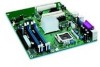
Desktop Board Features Table 3. Label A B C D E F G H I J K L M N O P Q R S T U V Desktop Boards D915PGN and D915PCY Components Description PCI Express x1 connectors Front panel audio header PCI Express x16 connector Rear chassis fan header 1 (fan speed control) Alternate power connector (1x4) 12 V processor core voltage connector (2x2) Processor socket Processor fan header (4-pin, controlled) Main power connector (2x12) Diskette drive connector Primary IDE connector Battery...
Desktop Board Features Table 3. Label A B C D E F G H I J K L M N O P Q R S T U V Desktop Boards D915PGN and D915PCY Components Description PCI Express x1 connectors Front panel audio header PCI Express x16 connector Rear chassis fan header 1 (fan speed control) Alternate power connector (1x4) 12 V processor core voltage connector (2x2) Processor socket Processor fan header (4-pin, controlled) Main power connector (2x12) Diskette drive connector Primary IDE connector Battery...

Product Guide
Page 15
... Express x1 connector Related Links Go to the following links for more information about: • Intel Desktop Board D915PGN/D915PSY/ D915PCY/D915PCM http://www.intel.com/design/motherbd http://support.intel.com/support/motherboards/desktop • Supported processors http://support.intel.com/support/motherboards/desktop • Audio software and utilities http://www.intel.com/design/motherbd • LAN software and drivers http://www...
... Express x1 connector Related Links Go to the following links for more information about: • Intel Desktop Board D915PGN/D915PSY/ D915PCY/D915PCM http://www.intel.com/design/motherbd http://support.intel.com/support/motherboards/desktop • Supported processors http://support.intel.com/support/motherboards/desktop • Audio software and utilities http://www.intel.com/design/motherbd • LAN software and drivers http://www...

Product Guide
Page 16
... Intel® processors for Desktop Board D915PGN/D915PSY/D915PCY/D915PCM http://support.intel.com/support/motherboards/desktop/ • Instructions on installing or upgrading the processor, page 32 in Chapter 2 • The location of the two power connectors, page 48 in the LGA775 package. The processor connects to the Intel desktop board through the LGA775 socket. Desktop Boards D915PGN, D915PSY, D915PCY, and D915PCM support a single Intel Pentium 4 processor in...
... Intel® processors for Desktop Board D915PGN/D915PSY/D915PCY/D915PCM http://support.intel.com/support/motherboards/desktop/ • Instructions on installing or upgrading the processor, page 32 in Chapter 2 • The location of the two power connectors, page 48 in the LGA775 package. The processor connects to the Intel desktop board through the LGA775 socket. Desktop Boards D915PGN, D915PSY, D915PCY, and D915PCM support a single Intel Pentium 4 processor in...

Product Guide
Page 17
... channel memory configurations defined in Table 5. Table 5. Table 6. Desktop Board Features Main Memory NOTE To be fully compliant with all applicable Intel® SDRAM memory specifications, the board should be populated with gold-plated contacts. • Support for normal operation. Desktop Board D915PCY/D915PCM Memory Configurations Memory Speed Processor FSB Frequency (MHz) Memory Speed Outcome (MHz) DDR2 533...
... channel memory configurations defined in Table 5. Table 5. Table 6. Desktop Board Features Main Memory NOTE To be fully compliant with all applicable Intel® SDRAM memory specifications, the board should be populated with gold-plated contacts. • Support for normal operation. Desktop Board D915PCY/D915PCM Memory Configurations Memory Speed Processor FSB Frequency (MHz) Memory Speed Outcome (MHz) DDR2 533...

Product Guide
Page 20
.../support/motherboards/desktop RJ-45 LAN Connector LEDs Two LEDs are backward compatible with another computer on Intel's World Wide Web site at USB 1.1 speeds. Enhanced IDE Interface The ICH6's IDE interface handles the exchange of information between the processor and peripheral devices like ...requirements, even if no device or a low-speed USB device is selected. Intel Desktop Board D915PGN/D915PSY/D915PCY/D915PCM Product Guide LAN Subsystem Software For LAN software and drivers, refer to the D915PGN/D915PSY/D915PCY/D915PCM link on the LAN. Table 7. On (steady state) On (brighter ...
.../support/motherboards/desktop RJ-45 LAN Connector LEDs Two LEDs are backward compatible with another computer on Intel's World Wide Web site at USB 1.1 speeds. Enhanced IDE Interface The ICH6's IDE interface handles the exchange of information between the processor and peripheral devices like ...requirements, even if no device or a low-speed USB device is selected. Intel Desktop Board D915PGN/D915PSY/D915PCY/D915PCM Product Guide LAN Subsystem Software For LAN software and drivers, refer to the D915PGN/D915PSY/D915PCY/D915PCM link on the LAN. Table 7. On (steady state) On (brighter ...
Product Guide
Page 23
... line for the location of delivering adequate +5 V standby current. Fan Speed Control (Intel® Precision Cooling Technology) Intel Precision Cooling Technology automatically adjusts the processor fan speed based on the processor temperature and adjusts the chassis fan speeds depending on desktop boards D915PGN and D915PCY are controlled. The overall system noise reduction will appear to be off...
... line for the location of delivering adequate +5 V standby current. Fan Speed Control (Intel® Precision Cooling Technology) Intel Precision Cooling Technology automatically adjusts the processor fan speed based on the processor temperature and adjusts the chassis fan speeds depending on desktop boards D915PGN and D915PCY are controlled. The overall system noise reduction will appear to be off...

Product Guide
Page 27
Follow these guidelines before you open the computer or perform any of the computer chassis. 27 Some circuitry on the board can continue to operate even though the front panel power button is not available, you can damage components. Perform the procedures... and a conductive foam pad. If such a station is off. 2 Installing and Replacing Desktop Board Components This chapter tells you how to: • Install the I/O shield • Install and remove the desktop board • Install and remove a processor and memory • Install and remove a x16 PCI Express card • Connect the ...
Follow these guidelines before you open the computer or perform any of the computer chassis. 27 Some circuitry on the board can continue to operate even though the front panel power button is not available, you can damage components. Perform the procedures... and a conductive foam pad. If such a station is off. 2 Installing and Replacing Desktop Board Components This chapter tells you how to: • Install the I/O shield • Install and remove the desktop board • Install and remove a processor and memory • Install and remove a x16 PCI Express card • Connect the ...

Product Guide
Page 28
...(like processors, voltage regulators, and heat sinks) • Damage to wires that your computer meets safety and regulatory requirements. Pay close attention to find out how you to refer computer servicing to meet safety and regulatory requirements when installing this board. Intel Desktop Board D915PGN/D915PSY/D915PCY/D915PCM ...follow these instructions and the instructions provided by chassis and module suppliers, you install and test the Intel desktop board, observe all of these instructions and the instructions supplied with these guidelines to qualified technical personnel.
...(like processors, voltage regulators, and heat sinks) • Damage to wires that your computer meets safety and regulatory requirements. Pay close attention to find out how you to refer computer servicing to meet safety and regulatory requirements when installing this board. Intel Desktop Board D915PGN/D915PSY/D915PCY/D915PCM ...follow these instructions and the instructions provided by chassis and module suppliers, you install and test the Intel desktop board, observe all of these instructions and the instructions supplied with these guidelines to qualified technical personnel.

Product Guide
Page 32
... page 24). Lift the load plate. Intel Desktop Board D915PGN/D915PSY/D915PCY/D915PCM Product Guide Installing and Removing a Processor Instructions on how to install the processor to do so could damage the processor and the board. Failure to the desktop board are given below. B A Figure 6. C D D Figure 7. Installing a Processor CAUTION Before installing or removing the processor, make sure that AC power has been...
... page 24). Lift the load plate. Intel Desktop Board D915PGN/D915PSY/D915PCY/D915PCM Product Guide Installing and Removing a Processor Instructions on how to install the processor to do so could damage the processor and the board. Failure to the desktop board are given below. B A Figure 6. C D D Figure 7. Installing a Processor CAUTION Before installing or removing the processor, make sure that AC power has been...

Product Guide
Page 33
... removed from the socket (see Figure 8, E). Remove the Protective Cover 5. Installing and Replacing Desktop Board Components 4. E Figure 8. Figure 9. Do not discard the protective cover. Always replace the processor cover if the processor is removed from the Protective Cover 33 Hold the processor only at the edges, being careful not to touch the bottom of the...
... removed from the socket (see Figure 8, E). Remove the Protective Cover 5. Installing and Replacing Desktop Board Components 4. E Figure 8. Figure 9. Do not discard the protective cover. Always replace the processor cover if the processor is removed from the Protective Cover 33 Hold the processor only at the edges, being careful not to touch the bottom of the...
Product Guide
Page 34
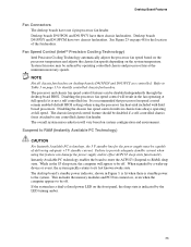
... 10. For instructions on the load plate (Figure 11, I Figure 11. Intel Desktop Board D915PGN/D915PSY/D915PCY/D915PCM Product Guide 6. J I ) close and engage the socket lever (Figure 11, J). Close the Load Plate Installing the Processor Fan Heat Sink Desktop Board D915PGN/D915PSY/D915PCY/D915PCM has an integrated processor fan heat sink retention mechanism (RM). Make sure fingers align to...
... 10. For instructions on the load plate (Figure 11, I Figure 11. Intel Desktop Board D915PGN/D915PSY/D915PCY/D915PCM Product Guide 6. J I ) close and engage the socket lever (Figure 11, J). Close the Load Plate Installing the Processor Fan Heat Sink Desktop Board D915PGN/D915PSY/D915PCY/D915PCM has an integrated processor fan heat sink retention mechanism (RM). Make sure fingers align to...

Product Guide
Page 35
... to remove the processor fan heat sink and processor, refer to the processor installation manual or the Intel World Wide Web site at: http://support.intel.com/support/processors/pentium4/intnotes478.htm 35 Connecting the Processor Fan Heat Sink Cable to the 4-pin processor fan connector (see Figure 12). Installing and Replacing Desktop Board Components Connecting the Processor Fan Heat Sink...
... to remove the processor fan heat sink and processor, refer to the processor installation manual or the Intel World Wide Web site at: http://support.intel.com/support/processors/pentium4/intnotes478.htm 35 Connecting the Processor Fan Heat Sink Cable to the 4-pin processor fan connector (see Figure 12). Installing and Replacing Desktop Board Components Connecting the Processor Fan Heat Sink...

Product Guide
Page 48
Connect chassis fan cables to the 4-pin processor fan header on the board. Intel Desktop Board D915PGN/D915PSY/D915PCY/D915PCM Product Guide Connecting Fan and Power Cables Connecting Fan Cables See Figure 23 for fan locations. Location of Fan Headers 43 2 1 B OM16844 48 Connect the processor's fan heat sink cable to the 3-pin fan headers. 3 21 A 3 21 B 43 2 1 A Figure 23.
Connect chassis fan cables to the 4-pin processor fan header on the board. Intel Desktop Board D915PGN/D915PSY/D915PCY/D915PCM Product Guide Connecting Fan and Power Cables Connecting Fan Cables See Figure 23 for fan locations. Location of Fan Headers 43 2 1 B OM16844 48 Connect the processor's fan heat sink cable to the 3-pin fan headers. 3 21 A 3 21 B 43 2 1 A Figure 23.

Product Guide
Page 49
...CAUTION Failure to use an ATX12V power supply, or not connecting the 12 V (2x2) processor core voltage power supply connector to the desktop board may result in "Before You Begin" on the desktop board is recommended with ATX12V power supplies with 2x10 power connections. Observe the precautions in damage to...Power Supply Cables The 2x12 main power connector on page 27. 2. Connect the main power supply cable to the desktop board and/or power supply. Connect the 12 V processor core voltage power supply cable to the 1x4 connector. 3. Figure 24 shows the location of the 1x4 power ...
...CAUTION Failure to use an ATX12V power supply, or not connecting the 12 V (2x2) processor core voltage power supply connector to the desktop board may result in "Before You Begin" on the desktop board is recommended with ATX12V power supplies with 2x10 power connections. Observe the precautions in damage to...Power Supply Cables The 2x12 main power connector on page 27. 2. Connect the main power supply cable to the desktop board and/or power supply. Connect the 12 V processor core voltage power supply cable to the 1x4 connector. 3. Figure 24 shows the location of the 1x4 power ...

Product Guide
Page 50
OM16851 50 Observe the precautions in "Before You Begin" on page 27. 2. Connect the main power supply cable to the 2x2 connector. 3. Connect the 12 V processor core voltage power supply cable to the 2x12 connector. Connecting 2x12 Power Supply Cables 1. Intel Desktop Board D915PGN/D915PSY/D915PCY/D915PCM Product Guide Connecting 2x12 Power Supply Cables If you have a 2x12 power supply, follow the instruction below. Figure 25 shows the location of the power connectors for a 2x12 power supply. 1 2 2X12 Figure 25.
OM16851 50 Observe the precautions in "Before You Begin" on page 27. 2. Connect the main power supply cable to the 2x2 connector. 3. Connect the 12 V processor core voltage power supply cable to the 2x12 connector. Connecting 2x12 Power Supply Cables 1. Intel Desktop Board D915PGN/D915PSY/D915PCY/D915PCM Product Guide Connecting 2x12 Power Supply Cables If you have a 2x12 power supply, follow the instruction below. Figure 25 shows the location of the power connectors for a 2x12 power supply. 1 2 2X12 Figure 25.


