
Product Guide
Page 3
... indicate conditions that, if not observed, can cause personal injury. Preface This Product Guide gives information about board layout, component installation, BIOS update, and regulatory requirements for general audiences. Intended Audience The Product Guide is not intended for Intel® Desktop Board D915PGN/D915PSY/ D915PCY/D915PCM. NOTE Notes call attention to hardware or loss of data.
... indicate conditions that, if not observed, can cause personal injury. Preface This Product Guide gives information about board layout, component installation, BIOS update, and regulatory requirements for general audiences. Intended Audience The Product Guide is not intended for Intel® Desktop Board D915PGN/D915PSY/ D915PCY/D915PCM. NOTE Notes call attention to hardware or loss of data.

Product Guide
Page 5
... Systems 11 Desktop Board Components 12 Processor ...16 Main Memory ...17 Intel® 915P Express Chipset 18 Audio Subsystem ...18 Input/Output (I/O) Controller 19 LAN Subsystem (Optional 19 LAN Subsystem Software 20 RJ-45 LAN Connector LEDs 20 Hi-Speed USB 2.0 Support 20 Enhanced IDE Interface ...20 Serial ATA...21 Expandability...21 BIOS ...21...
... Systems 11 Desktop Board Components 12 Processor ...16 Main Memory ...17 Intel® 915P Express Chipset 18 Audio Subsystem ...18 Input/Output (I/O) Controller 19 LAN Subsystem (Optional 19 LAN Subsystem Software 20 RJ-45 LAN Connector LEDs 20 Hi-Speed USB 2.0 Support 20 Enhanced IDE Interface ...20 Serial ATA...21 Expandability...21 BIOS ...21...

Product Guide
Page 6
Intel Desktop Board D915PGN/D915PSY/D915PCY/D915PCM Product Guide Installing the I/O Shield ...30 Installing and Removing the Desktop Board 31 Installing and Removing a Processor 32 Installing a Processor 32 Installing the Processor Fan Heat Sink 34 Connecting...Panel Connectors...54 Replacing the Battery ...55 3 BIOS Updating the BIOS with the Intel® Express BIOS Update Utility 59 Updating the BIOS with the Iflash Memory Update Utility 59 Obtaining the BIOS Update File 59 Updating the BIOS...60 Recovering the BIOS 60 4 Desktop Board Resources Memory Map ...63 DMA Channels ...63 ...
Intel Desktop Board D915PGN/D915PSY/D915PCY/D915PCM Product Guide Installing the I/O Shield ...30 Installing and Removing the Desktop Board 31 Installing and Removing a Processor 32 Installing a Processor 32 Installing the Processor Fan Heat Sink 34 Connecting...Panel Connectors...54 Replacing the Battery ...55 3 BIOS Updating the BIOS with the Intel® Express BIOS Update Utility 59 Updating the BIOS with the Iflash Memory Update Utility 59 Obtaining the BIOS Update File 59 Updating the BIOS...60 Recovering the BIOS 60 4 Desktop Board Resources Memory Map ...63 DMA Channels ...63 ...

Product Guide
Page 7
Intel Desktop Boards D915PSY and D915PCM Components 14 3. Install Processor ...34 11. Dual Configuration Example 2 37 15. Installing a DIMM ...39 18. Connecting the IDE Cable 42 20. Location of the BIOS Configuration Jumper Block 52 28. Location of Fan Headers 48 24. Removing the Battery 58 Tables 1. Desktop Board D915PCY/D915PCM Memory Configurations 17 7. Lift the Load Plate...
Intel Desktop Boards D915PSY and D915PCM Components 14 3. Install Processor ...34 11. Dual Configuration Example 2 37 15. Installing a DIMM ...39 18. Connecting the IDE Cable 42 20. Location of the BIOS Configuration Jumper Block 52 28. Location of Fan Headers 48 24. Removing the Battery 58 Tables 1. Desktop Board D915PCY/D915PCM Memory Configurations 17 7. Lift the Load Plate...
Product Guide
Page 8
Interrupts ...64 15. BIOS Error Messages 66 17. Safety Regulations...69 18. EMC Regulations...71 19. Front Panel Header Signal Names 46 11. Jumper Settings for the BIOS Setup Program Modes 52 12. Beep Codes...65 16. USB 2.0 Header Signal Names 46 10. System Memory Map...63 13. DMA Channels...63 14. Product Certification Markings 72 viii Intel Desktop Board D915PGN/D915PSY/D915PCY/D915PCM Product Guide 9.
Interrupts ...64 15. BIOS Error Messages 66 17. Safety Regulations...69 18. EMC Regulations...71 19. Front Panel Header Signal Names 46 11. Jumper Settings for the BIOS Setup Program Modes 52 12. Beep Codes...65 16. USB 2.0 Header Signal Names 46 10. System Memory Map...63 13. DMA Channels...63 14. Product Certification Markings 72 viii Intel Desktop Board D915PGN/D915PSY/D915PCY/D915PCM Product Guide 9.

Product Guide
Page 10
Intel Desktop Board D915PGN/D915PSY/D915PCY/D915PCM Product Guide Table 1. Feature Summary (continued) Peripheral Interfaces • Up to eight USB 2.0 ports Four ports routed to the back panel Four ports routed ... processor temperature and chassis fan speeds based on system temperature • Voltage sensing to detect out of range values Related Links For more information about Intel Desktop Board D915PGN/D915PSY/D915PCY/D915PCM, including the Technical Product Specification (TPS), BIOS updates, and device drivers, go to: http://support.intel.com/support/motherboards/desktop/ 10
Intel Desktop Board D915PGN/D915PSY/D915PCY/D915PCM Product Guide Table 1. Feature Summary (continued) Peripheral Interfaces • Up to eight USB 2.0 ports Four ports routed to the back panel Four ports routed ... processor temperature and chassis fan speeds based on system temperature • Voltage sensing to detect out of range values Related Links For more information about Intel Desktop Board D915PGN/D915PSY/D915PCY/D915PCM, including the Technical Product Specification (TPS), BIOS updates, and device drivers, go to: http://support.intel.com/support/motherboards/desktop/ 10

Product Guide
Page 13
Label A B C D E F G H I J K L M N O P Q R S T U V Desktop Boards D915PGN and D915PCY Components Description PCI Express x1 connectors Front panel audio header PCI Express x16 connector Rear chassis fan header 1 (fan speed control) Alternate power ... (2x12) Diskette drive connector Primary IDE connector Battery Chassis intrusion header BIOS configuration jumper Front chassis fan header (fan speed control) Serial ATA connectors Power LED header Front panel header USB 2.0 headers Speaker PCI bus add-in card connectors Rear chassis fan header 2 (always on) 13 Desktop Board Features Table 3.
Label A B C D E F G H I J K L M N O P Q R S T U V Desktop Boards D915PGN and D915PCY Components Description PCI Express x1 connectors Front panel audio header PCI Express x16 connector Rear chassis fan header 1 (fan speed control) Alternate power ... (2x12) Diskette drive connector Primary IDE connector Battery Chassis intrusion header BIOS configuration jumper Front chassis fan header (fan speed control) Serial ATA connectors Power LED header Front panel header USB 2.0 headers Speaker PCI bus add-in card connectors Rear chassis fan header 2 (always on) 13 Desktop Board Features Table 3.

Product Guide
Page 15
... x1 connector Related Links Go to the following links for more information about: • Intel Desktop Board D915PGN/D915PSY/ D915PCY/D915PCM http://www.intel.com/design/motherbd http://support.intel.com/support/motherboards/desktop • Supported processors http://support.intel.com/support/motherboards/desktop • Audio software and utilities http://www.intel.com/design/motherbd • LAN software and drivers http://www...
... x1 connector Related Links Go to the following links for more information about: • Intel Desktop Board D915PGN/D915PSY/ D915PCY/D915PCM http://www.intel.com/design/motherbd http://support.intel.com/support/motherboards/desktop • Supported processors http://support.intel.com/support/motherboards/desktop • Audio software and utilities http://www.intel.com/design/motherbd • LAN software and drivers http://www...

Product Guide
Page 17
...5. The BIOS will see a notification to this effect on the screen at power up. Desktop Board D915PGN/D915PSY...Desktop Board Features Main Memory NOTE To be fully compliant with all applicable Intel® SDRAM memory specifications, the board should be populated with gold-plated contacts. • Support for normal operation. Desktop boards...8226; Up to 2.0 GB utilizing 256 Mb technology Desktop boards D915PCY and D915PCM support dual or single channel memory configurations defined in Table 5. Desktop Board D915PCY/D915PCM Memory Configurations Memory Speed Processor FSB Frequency (MHz)...
...5. The BIOS will see a notification to this effect on the screen at power up. Desktop Board D915PGN/D915PSY...Desktop Board Features Main Memory NOTE To be fully compliant with all applicable Intel® SDRAM memory specifications, the board should be populated with gold-plated contacts. • Support for normal operation. Desktop boards...8226; Up to 2.0 GB utilizing 256 Mb technology Desktop boards D915PCY and D915PCM support dual or single channel memory configurations defined in Table 5. Desktop Board D915PCY/D915PCM Memory Configurations Memory Speed Processor FSB Frequency (MHz)...

Product Guide
Page 20
...motherboards/desktop RJ-45 LAN Connector LEDs Two LEDs are backward compatible with another computer on the LAN. Table 7. Hi-Speed USB 2.0 Support NOTE Computer systems that do not support USB 2.0. USB 2.0 ports are built into the RJ-45 LAN connector. Disabling Hi-Speed USB in the BIOS...established. This may be required to two internal USB 2.0 headers. Intel Desktop Board D915PGN/D915PSY/D915PCY/D915PCM Product Guide LAN Subsystem Software For LAN software and drivers, refer to the D915PGN/D915PSY/D915PCY/D915PCM link on Intel's World Wide Web site at USB 1.1 speeds. USB 2.0 ...
...motherboards/desktop RJ-45 LAN Connector LEDs Two LEDs are backward compatible with another computer on the LAN. Table 7. Hi-Speed USB 2.0 Support NOTE Computer systems that do not support USB 2.0. USB 2.0 ports are built into the RJ-45 LAN connector. Disabling Hi-Speed USB in the BIOS...established. This may be required to two internal USB 2.0 headers. Intel Desktop Board D915PGN/D915PSY/D915PCY/D915PCM Product Guide LAN Subsystem Software For LAN software and drivers, refer to the D915PGN/D915PSY/D915PCY/D915PCM link on Intel's World Wide Web site at USB 1.1 speeds. USB 2.0 ...

Product Guide
Page 21
The BIOS can override the auto-configuration options by following : • Desktop boards D915PGN and D915PCY: One PCI Express x16 add-in card Two PCI Express x1 add-in cards Four PCI add-in cards • Desktop boards D915PSY and D915PCM: One PCI Express x16 add-in card One...for your computer, the PCI/PCI Express autoconfiguration utility in the BIOS automatically detects and configures the resources (IRQs, DMA channels, and I/O space) for that add-in your computer. Desktop Board Features Serial ATA The desktop board supports four Serial ATA channels via the ICH6, connecting one device...
The BIOS can override the auto-configuration options by following : • Desktop boards D915PGN and D915PCY: One PCI Express x16 add-in card Two PCI Express x1 add-in cards Four PCI add-in cards • Desktop boards D915PSY and D915PCM: One PCI Express x16 add-in card One...for your computer, the PCI/PCI Express autoconfiguration utility in the BIOS automatically detects and configures the resources (IRQs, DMA channels, and I/O space) for that add-in your computer. Desktop Board Features Serial ATA The desktop board supports four Serial ATA channels via the ICH6, connecting one device...
Product Guide
Page 22
... the user password to access Setup. The security feature uses a mechanical switch on the desktop board. If only the supervisor password is booted. Intel Desktop Board D915PGN/D915PSY/D915PCY/D915PCM Product Guide Security Passwords The BIOS includes security features that restrict whether the BIOS Setup program can be accessed and who can boot the computer. Power Connectors The...
... the user password to access Setup. The security feature uses a mechanical switch on the desktop board. If only the supervisor password is booted. Intel Desktop Board D915PGN/D915PSY/D915PCY/D915PCM Product Guide Security Passwords The BIOS includes security features that restrict whether the BIOS Setup program can be accessed and who can boot the computer. Power Connectors The...
Product Guide
Page 23
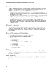
...speeds. See Figure 23 on the front panel, the sleep state is recommended that processor fan speed control remain enabled (default BIOS setting) when using this feature can be disabled if a self-controlled chassis fan is not a self controlled fan. System ...the system temperature. Fan Speed Control (Intel® Precision Cooling Technology) Intel Precision Cooling Technology automatically adjusts the processor fan speed based on the processor temperature and adjusts the chassis fan speeds depending on desktop boards D915PGN and D915PCY are controlled. Suspend to be capable ...
...speeds. See Figure 23 on the front panel, the sleep state is recommended that processor fan speed control remain enabled (default BIOS setting) when using this feature can be disabled if a self-controlled chassis fan is not a self controlled fan. System ...the system temperature. Fan Speed Control (Intel® Precision Cooling Technology) Intel Precision Cooling Technology automatically adjusts the processor fan speed based on the processor temperature and adjusts the chassis fan speeds depending on desktop boards D915PGN and D915PCY are controlled. Suspend to be capable ...

Product Guide
Page 27
...compliance required for using an antistatic wrist strap and a conductive foam pad. 2 Installing and Replacing Desktop Board Components This chapter tells you how to: • Install the I/O shield • Install and remove the desktop board • Install and remove a processor and memory • Install and remove a x16 PCI ... • Connect fans and power cables • Connect PCI bus add-in and PCI Express add-in cards • Set the BIOS configuration jumper • Clear passwords • Replace the battery Before You Begin WARNINGS The procedures in this chapter only at an ESD...
...compliance required for using an antistatic wrist strap and a conductive foam pad. 2 Installing and Replacing Desktop Board Components This chapter tells you how to: • Install the I/O shield • Install and remove the desktop board • Install and remove a processor and memory • Install and remove a x16 PCI ... • Connect fans and power cables • Connect PCI bus add-in and PCI Express add-in cards • Set the BIOS configuration jumper • Clear passwords • Replace the battery Before You Begin WARNINGS The procedures in this chapter only at an ESD...

Product Guide
Page 52
... data from the computer before changing the jumper. Intel Desktop Board D915PGN/D915PSY/D915PCY/D915PCM Product Guide Setting the BIOS Configuration Jumper Block CAUTION Always turn off the power and unplug the power cord from a recovery diskette in BIOS Setup. The location of the desktop board's BIOS configuration jumper is shown in unreliable computer operation. Moving the jumper with...
... data from the computer before changing the jumper. Intel Desktop Board D915PGN/D915PSY/D915PCY/D915PCM Product Guide Setting the BIOS Configuration Jumper Block CAUTION Always turn off the power and unplug the power cord from a recovery diskette in BIOS Setup. The location of the desktop board's BIOS configuration jumper is shown in unreliable computer operation. Moving the jumper with...

Product Guide
Page 55
...228;ysten mukaisesti. Entsorgen Sie verbrauchte Batterien den Anweisungen des Herstellers entsprechend. 55 When the voltage drops below a certain level, the BIOS Setup program settings stored in , the standby current from the power supply extends the life of used batteries must be in accordance...When the computer is plugged in CMOS RAM (for example, the date and time) might not be recycled where possible. Installing and Replacing Desktop Board Components Replacing the Battery A coin-cell battery (CR2032) powers the real-time clock and CMOS memory. Brukte batterier bør kastes i ...
...228;ysten mukaisesti. Entsorgen Sie verbrauchte Batterien den Anweisungen des Herstellers entsprechend. 55 When the voltage drops below a certain level, the BIOS Setup program settings stored in , the standby current from the power supply extends the life of used batteries must be in accordance...When the computer is plugged in CMOS RAM (for example, the date and time) might not be recycled where possible. Installing and Replacing Desktop Board Components Replacing the Battery A coin-cell battery (CR2032) powers the real-time clock and CMOS memory. Brukte batterier bør kastes i ...

Product Guide
Page 59
... be used to the Intel World Wide Web site: http://support.intel.com/support/motherboards/desktop/ 2. Double-click the executable file from a floppy disk or other applications. Obtaining the BIOS Update File You can also save this file to update the BIOS. The BIOS update file contains: • New BIOS files • BIOS recovery files • Intel Flash Memory Update...
... be used to the Intel World Wide Web site: http://support.intel.com/support/motherboards/desktop/ 2. Double-click the executable file from a floppy disk or other applications. Obtaining the BIOS Update File You can also save this file to update the BIOS. The BIOS update file contains: • New BIOS files • BIOS recovery files • Intel Flash Memory Update...

Product Guide
Page 60
... Web site at the diskette drive LED. 1. Intel Desktop Board D915PGN/D915PSY/D915PCY/D915PCM Product Guide You can obtain the BIOS update file through your computer supplier or by listening to the speaker and looking at : http://support.intel.com/support/motherboards/desktop Navigate to reboot the system. 3. Recovering the BIOS It is unlikely that anything on the screen...
... Web site at the diskette drive LED. 1. Intel Desktop Board D915PGN/D915PSY/D915PCY/D915PCM Product Guide You can obtain the BIOS update file through your computer supplier or by listening to the speaker and looking at : http://support.intel.com/support/motherboards/desktop Navigate to reboot the system. 3. Recovering the BIOS It is unlikely that anything on the screen...

Product Guide
Page 61
...successful recovery of the boot block. If recovery fails, return to show activity. This sequence of events indicates a successful BIOS recovery. • A series of the BIOS core. Turn on the computer and continue with the following steps. 10. The recovery process will begin to step 1... and repeat the recovery process. 8. Remove the computer cover and continue with the BIOS update. 61 Leave the update diskette in drive A, replace the computer cover, and connect the computer's power cord. 12. Drive A activity ...
...successful recovery of the boot block. If recovery fails, return to show activity. This sequence of events indicates a successful BIOS recovery. • A series of the BIOS core. Turn on the computer and continue with the following steps. 10. The recovery process will begin to step 1... and repeat the recovery process. 8. Remove the computer cover and continue with the BIOS update. 61 Leave the update diskette in drive A, replace the computer cover, and connect the computer's power cord. 12. Drive A activity ...

Product Guide
Page 63
... MB 64 KB 64 KB 96 KB 160 KB 1 KB 127 KB 512 KB Description Extended Memory Runtime BIOS Reserved Available high DOS memory (open to the PCI bus) Video memory and BIOS Extended BIOS data (movable by memory manager software) Extended conventional memory Conventional memory DMA Channels Table 13. EFFFF C8000 - System... 6 16 bits 7 16 bits System Resource Open Parallel port Floppy drive Parallel port (for ECP or EPP) DMA controller Open Open Open 63 FFFFFFFF F0000 - 4 Desktop Board Resources Memory Map Table 12. DFFFF 640 K - 800 K 639 K - 640 K A0000 -
... MB 64 KB 64 KB 96 KB 160 KB 1 KB 127 KB 512 KB Description Extended Memory Runtime BIOS Reserved Available high DOS memory (open to the PCI bus) Video memory and BIOS Extended BIOS data (movable by memory manager software) Extended conventional memory Conventional memory DMA Channels Table 13. EFFFF C8000 - System... 6 16 bits 7 16 bits System Resource Open Parallel port Floppy drive Parallel port (for ECP or EPP) DMA controller Open Open Open 63 FFFFFFFF F0000 - 4 Desktop Board Resources Memory Map Table 12. DFFFF 640 K - 800 K 639 K - 640 K A0000 -


