User Manual
Page 22
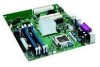
... • Up to run the BIOS Setup program after installing a Serial ATA or IDE device. Intel Desktop Board D915GEV/D915GUX/D915GAV/D915GAG Product Guide Enhanced IDE Interface The ICH6's IDE interface handles the exchange of information between the processor...auto-configuration options by following : • Desktop boards D915GAV and D915GEV ⎯ One PCI Express x16 add-in card ⎯ Two PCI Express x1 add-in cards ⎯ Four PCI add-in cards • Desktop boards D915GAG and D915GUX: ⎯ One PCI Express... PCI/PCI Express and IDE auto-configuration utilities, and the video BIOS.
... • Up to run the BIOS Setup program after installing a Serial ATA or IDE device. Intel Desktop Board D915GEV/D915GUX/D915GAV/D915GAG Product Guide Enhanced IDE Interface The ICH6's IDE interface handles the exchange of information between the processor...auto-configuration options by following : • Desktop boards D915GAV and D915GEV ⎯ One PCI Express x16 add-in card ⎯ Two PCI Express x1 add-in cards ⎯ Four PCI add-in cards • Desktop boards D915GAG and D915GUX: ⎯ One PCI Express... PCI/PCI Express and IDE auto-configuration utilities, and the video BIOS.

User Manual
Page 38
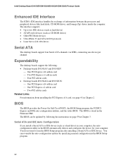
To make sure you have the correct DIMM, place the DIMM on the illustration in the DIMM sockets prior to installing the PCI Express video card to avoid interference with the memory retention mechanism. DDR DDR2 mm 1 2 3 4 5 6 7 8 9 10 11 12 13 OM16847 Figure 17. Intel Desktop Board D915GEV/D915GUX/D915GAV/D915GAG Product Guide Installing DIMMs CAUTION Install memory in Figure 17. Matching the Correct DIMM 38
To make sure you have the correct DIMM, place the DIMM on the illustration in the DIMM sockets prior to installing the PCI Express video card to avoid interference with the memory retention mechanism. DDR DDR2 mm 1 2 3 4 5 6 7 8 9 10 11 12 13 OM16847 Figure 17. Intel Desktop Board D915GEV/D915GUX/D915GAV/D915GAG Product Guide Installing DIMMs CAUTION Install memory in Figure 17. Matching the Correct DIMM 38
User Manual
Page 39
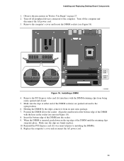
... it interferes with the keys in the socket (see Figure 18). Observe the precautions in place. 10. Remove the PCI Express video card if it was removed prior to the open position. 6. Make sure the clips are pushed outward to installing the DIMMs. 11. When the DIMM is ... the top edge of the DIMM socket(s) are firmly in "Before You Begin" on page 27. 2. Position the DIMM above the socket. Installing and Replacing Desktop Board Components 1. Channel A Channel B DIMM 0 DIMM 1 DIMM 0 DIMM 1 Figure 18.
... it interferes with the keys in the socket (see Figure 18). Observe the precautions in place. 10. Remove the PCI Express video card if it was removed prior to the open position. 6. Make sure the clips are pushed outward to installing the DIMMs. 11. When the DIMM is ... the top edge of the DIMM socket(s) are firmly in "Before You Begin" on page 27. 2. Position the DIMM above the socket. Installing and Replacing Desktop Board Components 1. Channel A Channel B DIMM 0 DIMM 1 DIMM 0 DIMM 1 Figure 18.

User Manual
Page 49
...power supplies with 2x10 connections when using PCI Express video cards that can consume up to 75 W. Connect the 12 V processor core voltage power supply cable to the 1x4 connector. 3. Observe the precautions in damage to the desktop board and/or power supply. OM16854 49 Connecting 2x10 Power... cable to the 2x10 connector. Connecting 2x10 Power Supply Cables The 2x12 main power connector on page 27. 2. Installing and Replacing Desktop Board Components Connecting Power Cables CAUTION Failure to use an ATX12V power supply, or not connecting the 12 V (2x2) processor core voltage...
...power supplies with 2x10 connections when using PCI Express video cards that can consume up to 75 W. Connect the 12 V processor core voltage power supply cable to the 1x4 connector. 3. Observe the precautions in damage to the desktop board and/or power supply. OM16854 49 Connecting 2x10 Power... cable to the 2x10 connector. Connecting 2x10 Power Supply Cables The 2x12 main power connector on page 27. 2. Installing and Replacing Desktop Board Components Connecting Power Cables CAUTION Failure to use an ATX12V power supply, or not connecting the 12 V (2x2) processor core voltage...
User Manual
Page 73
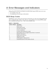
... Indicators Desktop Board D915GEV/D915GUX/D915GAV/D915GAG reports POST errors in two ways: • By sounding a beep code • By displaying an error message on the monitor BIOS Beep Codes The BIOS also issues a beep code (one long tone followed by two short tones) during POST if the video configuration fails (a faulty video card or no card...
... Indicators Desktop Board D915GEV/D915GUX/D915GAV/D915GAG reports POST errors in two ways: • By sounding a beep code • By displaying an error message on the monitor BIOS Beep Codes The BIOS also issues a beep code (one long tone followed by two short tones) during POST if the video configuration fails (a faulty video card or no card...


