
Product Guide
Page 3
Contents 1 Desktop Board Features Desktop Board Components 9 Processor ...11 Main Memory ...12 Intel® 850E Chipset ...12 Intel® 82850E Memory Controller Hub (MCH 12 Intel® 82801BA I/O Controller Hub (ICH2 13 Firmware Hub (FWH 13 Input/Output (I/O) Controller 13...Available Technology 18 Resume on Ring...20 2 Installing and Replacing Desktop Board Components Before You Begin ...21 Installing the I/O Shield ...22 Installing and Removing the Desktop Board 22 Installing a Processor ...24 Removing the Processor ...25 Installing Memory ...25 Removing Memory ...27 Installing an AGP...
Contents 1 Desktop Board Features Desktop Board Components 9 Processor ...11 Main Memory ...12 Intel® 850E Chipset ...12 Intel® 82850E Memory Controller Hub (MCH 12 Intel® 82801BA I/O Controller Hub (ICH2 13 Firmware Hub (FWH 13 Input/Output (I/O) Controller 13...Available Technology 18 Resume on Ring...20 2 Installing and Replacing Desktop Board Components Before You Begin ...21 Installing the I/O Shield ...22 Installing and Removing the Desktop Board 22 Installing a Processor ...24 Removing the Processor ...25 Installing Memory ...25 Removing Memory ...27 Installing an AGP...
Product Guide
Page 5
... Marking 76 Use Only for the BIOS Setup Program Modes (J9H2 30 6. Connecting the Processor Fan Cable to the Processor Fan Connector 24 9. Desktop Board D850EMV2 Power and Hardware Control Connectors 61 20. Front Panel Connectors ...64 Tables 1. Extended...the Battery...34 16. Desktop Board D850EMV2 Mounting Screw Holes 23 7. Desktop Board D850EMD2 Add-in Card and Peripheral Interface Connectors 63 22. Processors Supported by the Desktop Boards 11 3. Advanced Menu ...43 12. Desktop Board D850EMD2 Mounting Screw Holes 23 6. Installing a Processor...24 8. RDRAM and ...
... Marking 76 Use Only for the BIOS Setup Program Modes (J9H2 30 6. Connecting the Processor Fan Cable to the Processor Fan Connector 24 9. Desktop Board D850EMV2 Power and Hardware Control Connectors 61 20. Front Panel Connectors ...64 Tables 1. Extended...the Battery...34 16. Desktop Board D850EMV2 Mounting Screw Holes 23 7. Desktop Board D850EMD2 Add-in Card and Peripheral Interface Connectors 63 22. Processors Supported by the Desktop Boards 11 3. Advanced Menu ...43 12. Desktop Board D850EMD2 Mounting Screw Holes 23 6. Installing a Processor...24 8. RDRAM and ...
Product Guide
Page 7
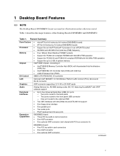
... panel USB connector One port routed to 2 GB of system memory Intel® 850E chipset, consisting of the Desktop Boards D850EMD2 and D850EMV2. Table 1. 1 Desktop Board Features ✏ NOTE The Desktop Board D850EMD2 layout was used for up to the optional CNR • Two IDE ...AGP cards Analog Devices Inc. Feature Summary Form Factors Processor Memory Chipset • microATX at 9.6 inches by 9.6 inches (D850EMD2 board) • ATX at 9.6 inches by 12 inches (D850EMV2 board) • Support for an Intel® Pentium® 4 processor in an mPGA478 socket • 533 MHz and ...
... panel USB connector One port routed to 2 GB of system memory Intel® 850E chipset, consisting of the Desktop Boards D850EMD2 and D850EMV2. Table 1. 1 Desktop Board Features ✏ NOTE The Desktop Board D850EMD2 layout was used for up to the optional CNR • Two IDE ...AGP cards Analog Devices Inc. Feature Summary Form Factors Processor Memory Chipset • microATX at 9.6 inches by 9.6 inches (D850EMD2 board) • ATX at 9.6 inches by 12 inches (D850EMV2 board) • Support for an Intel® Pentium® 4 processor in an mPGA478 socket • 533 MHz and ...

Product Guide
Page 10
...Intel 82801BA I/O Controller Hub (ICH2) K Processor socket AA NEC D720100AGM USB 2.0 controller L RIMM sockets BB PCI bus add-in card connectors M RIMM fan connector (fan 1) CC Communication and Networking Riser (CNR) (optional) N Power connector DD Chassis fan connector (fan 3) O Floppy drive connector P Primary IDE connector Figure 2. Intel Desktop Boards... D850EMD2 and D850EMV2 Product Guide Figure 2 shows the location of the major components on the Desktop Board D850EMV2.
...Intel 82801BA I/O Controller Hub (ICH2) K Processor socket AA NEC D720100AGM USB 2.0 controller L RIMM sockets BB PCI bus add-in card connectors M RIMM fan connector (fan 1) CC Communication and Networking Riser (CNR) (optional) N Power connector DD Chassis fan connector (fan 3) O Floppy drive connector P Primary IDE connector Figure 2. Intel Desktop Boards... D850EMD2 and D850EMV2 Product Guide Figure 2 shows the location of the major components on the Desktop Board D850EMV2.
Product Guide
Page 11
... 18 on .18 micron process in damage to desktop board specifications. The processor connects to the Intel desktop board World Wide Web site at: http://support.intel.com/support/motherboards/desktop For instructions on installing or upgrading the processor, see Chapter 2 on page 61 show the two power connector locations. 11 Desktop Board Features Processor CAUTION Failure to use an ATX12V power supply...
... 18 on .18 micron process in damage to desktop board specifications. The processor connects to the Intel desktop board World Wide Web site at: http://support.intel.com/support/motherboards/desktop For instructions on installing or upgrading the processor, see Chapter 2 on page 61 show the two power connector locations. 11 Desktop Board Features Processor CAUTION Failure to use an ATX12V power supply...

Product Guide
Page 14
... IDE Interface The ICH2's IDE interface handles the exchange of information between the processor and peripheral devices like hard disks, CD-ROM drives, and Iomega Zip† drives inside the computer. Intel Desktop Boards D850EMD2 and D850EMV2 Product Guide USB Support The desktop boards support up to the computer without an external hub. You can connect...
... IDE Interface The ICH2's IDE interface handles the exchange of information between the processor and peripheral devices like hard disks, CD-ROM drives, and Iomega Zip† drives inside the computer. Intel Desktop Boards D850EMD2 and D850EMV2 Product Guide USB Support The desktop boards support up to the computer without an external hub. You can connect...
Product Guide
Page 21
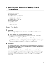
..., installed options, and configuration information. • Electrostatic discharge (ESD) can damage components. 2 Installing and Replacing Desktop Board Components This chapter tells you how to: • Install the I/O shield • Install and remove the desktop board • Install and remove a processor • Install and remove memory • Install and remove an AGP card • Connect the...
..., installed options, and configuration information. • Electrostatic discharge (ESD) can damage components. 2 Installing and Replacing Desktop Board Components This chapter tells you how to: • Install the I/O shield • Install and remove the desktop board • Install and remove a processor • Install and remove memory • Install and remove an AGP card • Connect the...

Product Guide
Page 24
... unplugging the power cord from the computer; OM13637 Figure 8. the standby power LED should not be lit (see Figure 7). 4. Intel Desktop Boards D850EMD2 and D850EMV2 Product Guide Installing a Processor CAUTION Before installing or removing the processor, make sure that the corner with the triangle marking (A) is aligned with the corner of the socket where the...
... unplugging the power cord from the computer; OM13637 Figure 8. the standby power LED should not be lit (see Figure 7). 4. Intel Desktop Boards D850EMD2 and D850EMV2 Product Guide Installing a Processor CAUTION Before installing or removing the processor, make sure that the corner with the triangle marking (A) is aligned with the corner of the socket where the...
Product Guide
Page 25
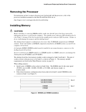
... a RIMM connector can damage the Desktop Boards D850EMD2 and D850EMV2. The standby power indicator LED should not be lit (see Figure 9). 128 MB RDRAM 128 MB RDRAM CRIMM CRIMM Figure 9. Failure to the processor installation manual or the Intel World Wide Web site at: http://support.intel.com/support/motherboards/desktop Installing Memory CAUTIONS Before installing or...
... a RIMM connector can damage the Desktop Boards D850EMD2 and D850EMV2. The standby power indicator LED should not be lit (see Figure 9). 128 MB RDRAM 128 MB RDRAM CRIMM CRIMM Figure 9. Failure to the processor installation manual or the Intel World Wide Web site at: http://support.intel.com/support/motherboards/desktop Installing Memory CAUTIONS Before installing or...

Product Guide
Page 40
Intel Desktop Boards D850EMD2 and D850EMV2 Product Guide Table 7 shows the function keys available for Management Boot Integrity Service (BIS) credentials. Setup only displays this menu in Table 8 is used to the Intel World Wide Web site at: http://developer.intel.com/design/security/index1.htm 40 Maintenance Menu Feature Processor Speed Clear All Passwords Clear BIS...
Intel Desktop Boards D850EMD2 and D850EMV2 Product Guide Table 7 shows the function keys available for Management Boot Integrity Service (BIS) credentials. Setup only displays this menu in Table 8 is used to the Intel World Wide Web site at: http://developer.intel.com/design/security/index1.htm 40 Maintenance Menu Feature Processor Speed Clear All Passwords Clear BIS...

Product Guide
Page 41
... becomes available when User Defined is used to memory as required. If selected here, will also display in the Advanced Menu as uncacheable by the processor. Well suited for applications not supporting Write Combining. 41 Selects Uncacheable Speculative Write-Combining (USWC) video memory cache mode. Full 32 byte contents of the...
... becomes available when User Defined is used to memory as required. If selected here, will also display in the Advanced Menu as uncacheable by the processor. Well suited for applications not supporting Write Combining. 41 Selects Uncacheable Speculative Write-Combining (USWC) video memory cache mode. Full 32 byte contents of the...
Product Guide
Page 42
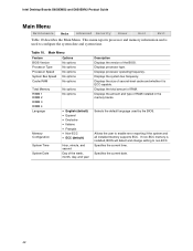
...version of RAM installed in the memory banks. Displays the size of RAM. Displays the amount and type of the BIOS. Displays processor type. Displays the total amount of second-level cache and whether it is installed, BIOS will detect and change setting to non-... frequency. Specifies the current date. 42 Specifies the current time. Intel Desktop Boards D850EMD2 and D850EMV2 Product Guide Main Menu Maintenance Main Advanced Security Power Boot Exit Table 10 describes the Main Menu. This menu reports processor and memory information and is used by the BIOS. Allows the...
...version of RAM installed in the memory banks. Displays the size of RAM. Displays the amount and type of the BIOS. Displays processor type. Displays the total amount of second-level cache and whether it is installed, BIOS will detect and change setting to non-... frequency. Specifies the current date. 42 Specifies the current time. Intel Desktop Boards D850EMD2 and D850EMV2 Product Guide Main Menu Maintenance Main Advanced Security Power Boot Exit Table 10 describes the Main Menu. This menu reports processor and memory information and is used by the BIOS. Allows the...
Product Guide
Page 60
... and D850EMV2 require an ATX12V compliant power supply to function according to the Intel 850E chipset and Pentium 4 processor. Both boards have two ATX12V compliant power supply connectors that are needed to provide extra power to desktop board specifications. Desktop Board D850EMD2 Power and Hardware Control Connectors 60 A B 1 2 4 1 3 C 1 G 1 1 D 20 10 11 1 E 1 F Item A B C D Description Chassis intrusion ATX12V power...
... and D850EMV2 require an ATX12V compliant power supply to function according to the Intel 850E chipset and Pentium 4 processor. Both boards have two ATX12V compliant power supply connectors that are needed to provide extra power to desktop board specifications. Desktop Board D850EMD2 Power and Hardware Control Connectors 60 A B 1 2 4 1 3 C 1 G 1 1 D 20 10 11 1 E 1 F Item A B C D Description Chassis intrusion ATX12V power...

Product Guide
Page 61
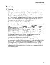
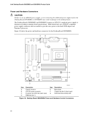
Desktop Board D850EMV2 Power and Hardware Control Connectors 61 A B C 1 1 2 4 1 3 D 1 1 1 E 20 10 11 1 F 1 Item A B C D H G Description Chassis fan (fan 3) Chassis intrusion ATX12V power Processor fan (CPU fan) (tach input) Item E F G H OM13632 Description RIMM fan (fan 1) (tach input) Main power Chassis fan (fan 2) SCSI hard drive activity LED Figure 19. Technical Reference Figure 19 shows the power and hardware connectors for the Desktop Board D850EMV2.
Desktop Board D850EMV2 Power and Hardware Control Connectors 61 A B C 1 1 2 4 1 3 D 1 1 1 E 20 10 11 1 F 1 Item A B C D H G Description Chassis fan (fan 3) Chassis intrusion ATX12V power Processor fan (CPU fan) (tach input) Item E F G H OM13632 Description RIMM fan (fan 1) (tach input) Main power Chassis fan (fan 2) SCSI hard drive activity LED Figure 19. Technical Reference Figure 19 shows the power and hardware connectors for the Desktop Board D850EMV2.
Product Guide
Page 69
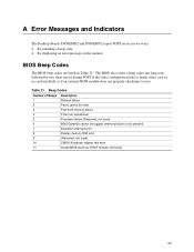
... test error Invalid BIOS (such as, POST module not found) 69 not used ) 8042 GateA20 cannot be reset First 64 K memory failure Timer not operational Processor failure (Reserved; Beep Codes Number of Beeps 1 2 3 4 5 6 7 8 9 10 11 Description Refresh failure Parity cannot be toggled (memory failure or ...faulty video card or no card installed) or if an external ROM module does not properly checksum to zero. A Error Messages and Indicators The Desktop Boards D850EMD2 and D850EMV2 report POST errors in two ways: • By sounding a beep code • By displaying an error message on the...
... test error Invalid BIOS (such as, POST module not found) 69 not used ) 8042 GateA20 cannot be reset First 64 K memory failure Timer not operational Processor failure (Reserved; Beep Codes Number of Beeps 1 2 3 4 5 6 7 8 9 10 11 Description Refresh failure Parity cannot be toggled (memory failure or ...faulty video card or no card installed) or if an external ROM module does not properly checksum to zero. A Error Messages and Indicators The Desktop Boards D850EMD2 and D850EMV2 report POST errors in two ways: • By sounding a beep code • By displaying an error message on the...

Product Guide
Page 75
...EMC testing and are not Class B EMC compliant before integration, then EMC testing is required on the chassis • Hot components (like processors, voltage regulators, and heat sinks) • Damage to wires that could be hazardous If the power supply and other modules pay close attention...suppliers, you increase safety risk and the possibility of noncompliance with these guidelines to find out how you install and test the desktop board, observe all warnings and cautions that instruct you do not follow these instructions and the instructions supplied with the chassis and associated...
...EMC testing and are not Class B EMC compliant before integration, then EMC testing is required on the chassis • Hot components (like processors, voltage regulators, and heat sinks) • Damage to wires that could be hazardous If the power supply and other modules pay close attention...suppliers, you increase safety risk and the possibility of noncompliance with these guidelines to find out how you install and test the desktop board, observe all warnings and cautions that instruct you do not follow these instructions and the instructions supplied with the chassis and associated...

Product Guide
Page 77
may require further evaluation. 77 Regulatory Compliance Use Only for Intended Applications All Intel desktop processor boards are evaluated as Information Technology Equipment (I.T.E.) for use in personal computers for other applications or environments, such as medical, industrial, alarm systems, test equipment, etc. The suitability of this product for installation in homes, offices, schools, computer rooms, and similar locations.
may require further evaluation. 77 Regulatory Compliance Use Only for Intended Applications All Intel desktop processor boards are evaluated as Information Technology Equipment (I.T.E.) for use in personal computers for other applications or environments, such as medical, industrial, alarm systems, test equipment, etc. The suitability of this product for installation in homes, offices, schools, computer rooms, and similar locations.


