

Product Guide
Page 2
...of this document, or other application in this product, contact: Intel Corporation 5200 N.E. Intel may cause undesired operation. Revision History Revision -001 -002 -003 Revision History First release of the Intel Desktop Boards D850EMD2 and D850EMV2 Product Guide. Le présent appareil numerique német ...may contain design defects or errors known as the property of the FCC Rules. Intel products are designed to the presented subject matter. The D850EMD2 and D850EMV2 desktop boards may cause the product to deviate from digital apparatus set out in the Radio Interference...
...of this document, or other application in this product, contact: Intel Corporation 5200 N.E. Intel may cause undesired operation. Revision History Revision -001 -002 -003 Revision History First release of the Intel Desktop Boards D850EMD2 and D850EMV2 Product Guide. Le présent appareil numerique német ...may contain design defects or errors known as the property of the FCC Rules. Intel products are designed to the presented subject matter. The D850EMD2 and D850EMV2 desktop boards may cause the product to deviate from digital apparatus set out in the Radio Interference...
Product Guide
Page 4
Intel Desktop Boards D850EMD2 and D850EMV2 Product Guide 3 Updating the BIOS Updating the BIOS with the Intel® Express BIOS Update Utility 35 Updating the BIOS with the Intel® Flash Memory Update Utility 35 Obtaining the BIOS Update File 35 Updating the BIOS...36 Recovering the ...58 Midboard Connectors 59 Audio Connectors 59 Power and Hardware Connectors 60 Add-In Card and Peripheral Interface Connectors 62 Front Panel Connectors 64 Desktop Board Resources 65 Memory Map ...65 DMA Channels ...65 I/O Map ...66 Interrupts ...68 A Error Messages and Indicators BIOS Beep Codes ......
Intel Desktop Boards D850EMD2 and D850EMV2 Product Guide 3 Updating the BIOS Updating the BIOS with the Intel® Express BIOS Update Utility 35 Updating the BIOS with the Intel® Flash Memory Update Utility 35 Obtaining the BIOS Update File 35 Updating the BIOS...36 Recovering the ...58 Midboard Connectors 59 Audio Connectors 59 Power and Hardware Connectors 60 Add-In Card and Peripheral Interface Connectors 62 Front Panel Connectors 64 Desktop Board Resources 65 Memory Map ...65 DMA Channels ...65 I/O Map ...66 Interrupts ...68 A Error Messages and Indicators BIOS Beep Codes ......
Product Guide
Page 5
...26 11. Location of the Standby Power Indicator 18 4. Desktop Board D850EMD2 Power and Hardware Control Connectors 60 19. Desktop Board D850EMD2 Add-in Card and Peripheral Interface Connectors 63 22. Desktop Board D850EMV2 Add-in Card and Peripheral Interface Connectors 62 21. Standby...19 5. Maintenance Menu ...40 9. Advanced Menu ...43 12. Desktop Board D850EMV2 Mounting Screw Holes 23 7. Feature Summary ...7 2. RJ-45 LAN Connector LEDs 17 4. Extended Configuration Submenu 41 10. Desktop Board D850EMV2 Components 10 3. RDRAM and CRIMM Installation 25 10. Removing the ...
...26 11. Location of the Standby Power Indicator 18 4. Desktop Board D850EMD2 Power and Hardware Control Connectors 60 19. Desktop Board D850EMD2 Add-in Card and Peripheral Interface Connectors 63 22. Desktop Board D850EMV2 Add-in Card and Peripheral Interface Connectors 62 21. Standby...19 5. Maintenance Menu ...40 9. Advanced Menu ...43 12. Desktop Board D850EMV2 Mounting Screw Holes 23 7. Feature Summary ...7 2. RJ-45 LAN Connector LEDs 17 4. Extended Configuration Submenu 41 10. Desktop Board D850EMV2 Components 10 3. RDRAM and CRIMM Installation 25 10. Removing the ...
Product Guide
Page 7
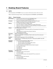
... Two ports routed to the front panel USB connector One port routed to 2 GB of system memory Intel® 850E chipset, consisting of the Desktop Boards D850EMD2 and D850EMV2. 1 Desktop Board Features ✏ NOTE The Desktop Board D850EMD2 layout was used for up to the optional CNR • Two IDE interfaces with Ultra DMA-33 and...
... Two ports routed to the front panel USB connector One port routed to 2 GB of system memory Intel® 850E chipset, consisting of the Desktop Boards D850EMD2 and D850EMV2. 1 Desktop Board Features ✏ NOTE The Desktop Board D850EMD2 layout was used for up to the optional CNR • Two IDE interfaces with Ultra DMA-33 and...
Product Guide
Page 8
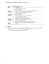
Feature Summary (continued) BIOS • Intel/AMI BIOS • 4 Mbit symmetrical flash memory • Support for SMBIOS Power Management • Support for Advanced Configuration and Power Interface (...• SCSI hard drive activity LED connector for the front panel • Speaker ✏ NOTE For information about Intel® desktop boards, including technical product specifications, BIOS updates, and device drivers, go to the Intel World Wide Web site at: http://support.intel.com/support/motherboards/desktop 8 Intel Desktop Boards D850EMD2 and D850EMV2 Product Guide Table 1.
Feature Summary (continued) BIOS • Intel/AMI BIOS • 4 Mbit symmetrical flash memory • Support for SMBIOS Power Management • Support for Advanced Configuration and Power Interface (...• SCSI hard drive activity LED connector for the front panel • Speaker ✏ NOTE For information about Intel® desktop boards, including technical product specifications, BIOS updates, and device drivers, go to the Intel World Wide Web site at: http://support.intel.com/support/motherboards/desktop 8 Intel Desktop Boards D850EMD2 and D850EMV2 Product Guide Table 1.

Product Guide
Page 10
Intel Desktop Boards D850EMD2 and D850EMV2 Product Guide Figure 2 shows the location of the major components on the Desktop Board D850EMV2. Desktop Board D850EMV2 Components 10 A B CD E F G DD H I CC J BB K AA L Z Y X M W V TR US P Q O N OM13619 A ADI AD1885 audio codec ... BIOS configuration jumper I Processor fan connector (CPU fan) (tachometer input) Y SCSI hard drive activity LED connector J Intel 82850E Memory Controller Hub (MCH) Z Intel 82801BA I/O Controller Hub (ICH2) K Processor socket AA NEC D720100AGM USB 2.0 controller L RIMM sockets BB PCI bus ...
Intel Desktop Boards D850EMD2 and D850EMV2 Product Guide Figure 2 shows the location of the major components on the Desktop Board D850EMV2. Desktop Board D850EMV2 Components 10 A B CD E F G DD H I CC J BB K AA L Z Y X M W V TR US P Q O N OM13619 A ADI AD1885 audio codec ... BIOS configuration jumper I Processor fan connector (CPU fan) (tachometer input) Y SCSI hard drive activity LED connector J Intel 82850E Memory Controller Hub (MCH) Z Intel 82801BA I/O Controller Hub (ICH2) K Processor socket AA NEC D720100AGM USB 2.0 controller L RIMM sockets BB PCI bus ...
Product Guide
Page 11
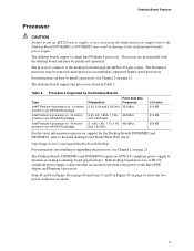
... MHz L2 Cache 512 KB 512 KB 256 KB For the latest information on processor support for the Desktop Boards D850EMD2 and D850EMV2, refer to the Intel desktop board World Wide Web site at: http://support.intel.com/support/motherboards/desktop For instructions on installing or upgrading the processor, see Chapter 2 on page 61 show the two power connector...
... MHz L2 Cache 512 KB 512 KB 256 KB For the latest information on processor support for the Desktop Boards D850EMD2 and D850EMV2, refer to the Intel desktop board World Wide Web site at: http://support.intel.com/support/motherboards/desktop For instructions on installing or upgrading the processor, see Chapter 2 on page 61 show the two power connector...

Product Guide
Page 12
...the following memory features: • Maximum of RDRAM memory • Support for a single AGP device 12 Intel Desktop Boards D850EMD2 and D850EMV2 Product Guide Main Memory The desktop boards have four 2.5 V memory module sockets that support these features: • Integrated dual Direct Rambus technology ...; Auto-detection of 32 RDRAM devices per channel • 128 MB (minimum) to the Desktop Board D850EMD2 or D850EMV2 link on this Intel World Wide Web site: http://support.intel.com/support/motherboards/desktop For information about installing memory, see Chapter 2 on page 21.
...the following memory features: • Maximum of RDRAM memory • Support for a single AGP device 12 Intel Desktop Boards D850EMD2 and D850EMV2 Product Guide Main Memory The desktop boards have four 2.5 V memory module sockets that support these features: • Integrated dual Direct Rambus technology ...; Auto-detection of 32 RDRAM devices per channel • 128 MB (minimum) to the Desktop Board D850EMD2 or D850EMV2 link on this Intel World Wide Web site: http://support.intel.com/support/motherboards/desktop For information about installing memory, see Chapter 2 on page 21.

Product Guide
Page 14
... connector (slot shared with UHCI. ✏ NOTE Computer systems that meets the requirements for a full-speed USB device. The desktop boards support the standard universal host controller interface (UHCI) and takes advantage of standard software drivers written to the cable. PCI Enhanced ...connector 14 To attach additional devices, connect an external hub to the computer without an external hub. Intel Desktop Boards D850EMD2 and D850EMV2 Product Guide USB Support The desktop boards support up to the optional CNR. You can connect five USB peripheral devices directly to either of ...
... connector (slot shared with UHCI. ✏ NOTE Computer systems that meets the requirements for a full-speed USB device. The desktop boards support the standard universal host controller interface (UHCI) and takes advantage of standard software drivers written to the cable. PCI Enhanced ...connector 14 To attach additional devices, connect an external hub to the computer without an external hub. Intel Desktop Boards D850EMD2 and D850EMV2 Product Guide USB Support The desktop boards support up to the optional CNR. You can connect five USB peripheral devices directly to either of ...
Product Guide
Page 16
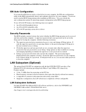
...can enter either the supervisor password or the user password to boot the computer. You do not need to the D850EMD2 and D850EMV2 link on whether the supervisor or user password was entered. • Setting a user password restricts who can override the .... • If both 10Base-T and 100Base-TX connectivity. Intel Desktop Boards D850EMD2 and D850EMV2 Product Guide IDE Auto Configuration If you must enter either password to access Setup. The password prompt is displayed before the computer is set , pressing at : http://support.intel.com/support/motherboards/desktop 16
...can enter either the supervisor password or the user password to boot the computer. You do not need to the D850EMD2 and D850EMV2 link on whether the supervisor or user password was entered. • Setting a user password restricts who can override the .... • If both 10Base-T and 100Base-TX connectivity. Intel Desktop Boards D850EMD2 and D850EMV2 Product Guide IDE Auto Configuration If you must enter either password to access Setup. The password prompt is displayed before the computer is set , pressing at : http://support.intel.com/support/motherboards/desktop 16

Product Guide
Page 18
... S3 (Suspend-to provide adequate standby current when using this feature can damage the power supply and/or affect ACPI S3 sleep state functionality. Intel Desktop Boards D850EMD2 and D850EMV2 Product Guide Instantly Available Technology CAUTION For Instantly Available technology, the 5 V standby line for the power supply must be able to provide enough standby...
... S3 (Suspend-to provide adequate standby current when using this feature can damage the power supply and/or affect ACPI S3 sleep state functionality. Intel Desktop Boards D850EMD2 and D850EMV2 Product Guide Instantly Available Technology CAUTION For Instantly Available technology, the 5 V standby line for the power supply must be able to provide enough standby...

Product Guide
Page 19
...added. Standby Current Requirements Instantly Available Current Support Estimate for integrated board components Estimate for add-on components (Add to integrated board components shown above) Description Total for the Desktop Board D850EMD2 or D850EMV2 PS/2 ports** PCI 2.2 slots (wake-enabled) PCI 2.2 slots...Sept 1991): • Keyboard @ 275 mA • Mouse @ 70 mA USB requirements are limited to the Intel® Desktop Board D850EMV2/D850EMD2 Technical Product Specification for a particular system configuration, standby current requirements of all additional wake-enabled devices' and ...
...added. Standby Current Requirements Instantly Available Current Support Estimate for integrated board components Estimate for add-on components (Add to integrated board components shown above) Description Total for the Desktop Board D850EMD2 or D850EMV2 PS/2 ports** PCI 2.2 slots (wake-enabled) PCI 2.2 slots...Sept 1991): • Keyboard @ 275 mA • Mouse @ 70 mA USB requirements are limited to the Intel® Desktop Board D850EMV2/D850EMD2 Technical Product Specification for a particular system configuration, standby current requirements of all additional wake-enabled devices' and ...

Product Guide
Page 20
Intel Desktop Boards D850EMD2 and D850EMV2 Product Guide Resume on Ring The operation of Resume on Ring can be summarized as follows: • Resumes operation from the ACPI S1 state • Requires only one call to access the computer • Detects incoming calls similarly for external and internal modems • Requires modem interrupt be unmasked for correct operation 20
Intel Desktop Boards D850EMD2 and D850EMV2 Product Guide Resume on Ring The operation of Resume on Ring can be summarized as follows: • Resumes operation from the ACPI S1 state • Requires only one call to access the computer • Detects incoming calls similarly for external and internal modems • Requires modem interrupt be unmasked for correct operation 20

Product Guide
Page 22
.... Figure 4 shows how the I/O shield is secured to your chassis manual for the locations of the mounting screw holes of each desktop board. The Desktop Board D850EMD2 is installed inside the chassis as shown in the following figure. Intel Desktop Boards D850EMD2 and D850EMV2 Product Guide Installing the I/O Shield ✏ NOTE Systems based on installing and removing the...
.... Figure 4 shows how the I/O shield is secured to your chassis manual for the locations of the mounting screw holes of each desktop board. The Desktop Board D850EMD2 is installed inside the chassis as shown in the following figure. Intel Desktop Boards D850EMD2 and D850EMV2 Product Guide Installing the I/O Shield ✏ NOTE Systems based on installing and removing the...

Product Guide
Page 23
OM13623 Figure 5. Desktop Board D850EMV2 Mounting Screw Holes 23 OM13622 Figure 6. Desktop Board D850EMD2 Mounting Screw Holes Figure 6 shows the location of the mounting holes for the Desktop Board D850EMV2. Installing and Replacing Desktop Board Components ✏ NOTES You will need a Phillips† (#2 bit) screwdriver. Figure 5 shows the location of the mounting holes for the Desktop Board D850EMD2. Refer to Appendix B on page 73 for regulatory requirements and installation instructions and precautions.
OM13623 Figure 5. Desktop Board D850EMV2 Mounting Screw Holes 23 OM13622 Figure 6. Desktop Board D850EMD2 Mounting Screw Holes Figure 6 shows the location of the mounting holes for the Desktop Board D850EMV2. Installing and Replacing Desktop Board Components ✏ NOTES You will need a Phillips† (#2 bit) screwdriver. Figure 5 shows the location of the mounting holes for the Desktop Board D850EMD2. Refer to Appendix B on page 73 for regulatory requirements and installation instructions and precautions.

Product Guide
Page 24
... page 18). OM13637 Figure 8. Connecting the Processor Fan Cable to do so could damage the processor and the desktop board. Failure to the Processor Fan Connector 24 Install the processor so that AC power has been removed by unplugging the ... the lever to the boxed processor manual or the Intel World Wide Web site at: http://support.intel.com/support/processors/pentium4/intnotes478.htm 6. Installing a Processor 5. mPGA478B mPGA478B mPGA478B A OM12078 Figure 7. Intel Desktop Boards D850EMD2 and D850EMV2 Product Guide Installing a Processor CAUTION Before installing or...
... page 18). OM13637 Figure 8. Connecting the Processor Fan Cable to do so could damage the processor and the desktop board. Failure to the Processor Fan Connector 24 Install the processor so that AC power has been removed by unplugging the ... the lever to the boxed processor manual or the Intel World Wide Web site at: http://support.intel.com/support/processors/pentium4/intnotes478.htm 6. Installing a Processor 5. mPGA478B mPGA478B mPGA478B A OM12078 Figure 7. Intel Desktop Boards D850EMD2 and D850EMV2 Product Guide Installing a Processor CAUTION Before installing or...
Product Guide
Page 25
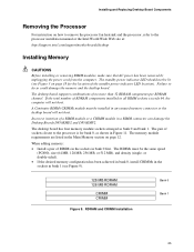
If the total number of a RIMM module or a CRIMM module in a RIMM connector can damage the Desktop Boards D850EMD2 and D850EMV2. or double-sided). • If the desired memory configuration has been achieved in bank 0, install CRIMMs in the sockets in all...Bank 1 25 The desktop board supports combinations of RIMMs in the sockets in the Main Memory section on how to remove the processor fan heatsink and the processor, refer to the processor installation manual or the Intel World Wide Web site at: http://support.intel.com/support/motherboards/desktop Installing Memory CAUTIONS ...
If the total number of a RIMM module or a CRIMM module in a RIMM connector can damage the Desktop Boards D850EMD2 and D850EMV2. or double-sided). • If the desired memory configuration has been achieved in bank 0, install CRIMMs in the sockets in all...Bank 1 25 The desktop board supports combinations of RIMMs in the sockets in the Main Memory section on how to remove the processor fan heatsink and the processor, refer to the processor installation manual or the Intel World Wide Web site at: http://support.intel.com/support/motherboards/desktop Installing Memory CAUTIONS ...
Product Guide
Page 26
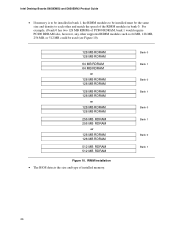
... RDRAM 128 MB RDRAM 256 MB RDRAM 256 MB RDRAM or 128 MB RDRAM 128 MB RDRAM 512 MB RDRAM 512 MB RDRAM Figure 10. Intel Desktop Boards D850EMD2 and D850EMV2 Product Guide • If memory is to be installed in bank 0.
... RDRAM 128 MB RDRAM 256 MB RDRAM 256 MB RDRAM or 128 MB RDRAM 128 MB RDRAM 512 MB RDRAM 512 MB RDRAM Figure 10. Intel Desktop Boards D850EMD2 and D850EMV2 Product Guide • If memory is to be installed in bank 0.

Product Guide
Page 28
...RM lever (D), as shown in Figure 12, until it is completely seated in the card. 3. Removing the AGP Card OM13625 28 The desktop board has an integrated AGP retention mechanism (RM). Follow these instructions to install an AGP card: 1. Removing the AGP Card Follow these instructions... RM pin. 3. Secure the card's metal bracket to the chassis back panel. 2. Place the AGP card in the AGP connector. 2. Intel Desktop Boards D850EMD2 and D850EMV2 Product Guide Installing an AGP Card The AGP connector supports 1.5 V 4X and 2X AGP cards. Remove the screw (B) that secures the card...
...RM lever (D), as shown in Figure 12, until it is completely seated in the card. 3. Removing the AGP Card OM13625 28 The desktop board has an integrated AGP retention mechanism (RM). Follow these instructions to install an AGP card: 1. Removing the AGP Card Follow these instructions... RM pin. 3. Secure the card's metal bracket to the chassis back panel. 2. Place the AGP card in the AGP connector. 2. Intel Desktop Boards D850EMD2 and D850EMV2 Product Guide Installing an AGP Card The AGP connector supports 1.5 V 4X and 2X AGP cards. Remove the screw (B) that secures the card...
Product Guide
Page 30
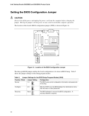
..., the BIOS displays the maintenance menu. The location of the BIOS Configuration Jumper The three-pin BIOS jumper enables the board configuration to be done in unreliable computer operation. The BIOS attempts to clear passwords. A recovery diskette is shown in ... 1 3 2-3 1 3 None 1 3 Configuration The BIOS uses current configuration information and passwords for the Setup program modes. Intel Desktop Boards D850EMD2 and D850EMV2 Product Guide Setting the BIOS Configuration Jumper CAUTION Always turn off the power and unplug the power cord from the computer before changing...
..., the BIOS displays the maintenance menu. The location of the BIOS Configuration Jumper The three-pin BIOS jumper enables the board configuration to be done in unreliable computer operation. The BIOS attempts to clear passwords. A recovery diskette is shown in ... 1 3 2-3 1 3 None 1 3 Configuration The BIOS uses current configuration information and passwords for the Setup program modes. Intel Desktop Boards D850EMD2 and D850EMV2 Product Guide Setting the BIOS Configuration Jumper CAUTION Always turn off the power and unplug the power cord from the computer before changing...