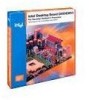

Product Guide
Page 2
...not provide any other countries. † Other names and brands may cause harmful interference to the EMC performance of the Intel Desktop Boards D850EMD2 and D850EMV2 Product Guide. Copies of documents and other intellectual property rights. This equipment generates, uses, and can ...Radio Interference Regulations of the Canadian Department of the Intel® Desktop Boards D850EMD2 and D850EMV2 Product Guide. The D850EMD2 and D850EMV2 desktop boards may contain design defects or errors known as the property of Intel Corporation or it subsidiaries in accordance with the instructions,...
...not provide any other countries. † Other names and brands may cause harmful interference to the EMC performance of the Intel Desktop Boards D850EMD2 and D850EMV2 Product Guide. Copies of documents and other intellectual property rights. This equipment generates, uses, and can ...Radio Interference Regulations of the Canadian Department of the Intel® Desktop Boards D850EMD2 and D850EMV2 Product Guide. The D850EMD2 and D850EMV2 desktop boards may contain design defects or errors known as the property of Intel Corporation or it subsidiaries in accordance with the instructions,...

Product Guide
Page 3
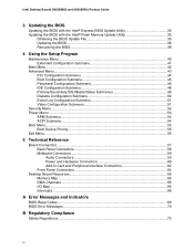
Contents 1 Desktop Board Features Desktop Board Components 9 Processor ...11 Main Memory ...12 Intel® 850E Chipset ...12 Intel® 82850E Memory Controller Hub (MCH 12 Intel® 82801BA I/O Controller Hub (ICH2 13 Firmware Hub (FWH 13 Input/Output (I/O) Controller 13... Features 17 Instantly Available Technology 18 Resume on Ring...20 2 Installing and Replacing Desktop Board Components Before You Begin ...21 Installing the I/O Shield ...22 Installing and Removing the Desktop Board 22 Installing a Processor ...24 Removing the Processor ...25 Installing Memory ...25 Removing...
Contents 1 Desktop Board Features Desktop Board Components 9 Processor ...11 Main Memory ...12 Intel® 850E Chipset ...12 Intel® 82850E Memory Controller Hub (MCH 12 Intel® 82801BA I/O Controller Hub (ICH2 13 Firmware Hub (FWH 13 Input/Output (I/O) Controller 13... Features 17 Instantly Available Technology 18 Resume on Ring...20 2 Installing and Replacing Desktop Board Components Before You Begin ...21 Installing the I/O Shield ...22 Installing and Removing the Desktop Board 22 Installing a Processor ...24 Removing the Processor ...25 Installing Memory ...25 Removing...
Product Guide
Page 4
Intel Desktop Boards D850EMD2 and D850EMV2 Product Guide 3 Updating the BIOS Updating the BIOS with the Intel® Express BIOS Update Utility 35 Updating the BIOS with the Intel® Flash Memory Update Utility 35 Obtaining the BIOS Update File 35 Updating the BIOS...36 Recovering the ...58 Midboard Connectors 59 Audio Connectors 59 Power and Hardware Connectors 60 Add-In Card and Peripheral Interface Connectors 62 Front Panel Connectors 64 Desktop Board Resources 65 Memory Map ...65 DMA Channels ...65 I/O Map ...66 Interrupts ...68 A Error Messages and Indicators BIOS Beep Codes ......
Intel Desktop Boards D850EMD2 and D850EMV2 Product Guide 3 Updating the BIOS Updating the BIOS with the Intel® Express BIOS Update Utility 35 Updating the BIOS with the Intel® Flash Memory Update Utility 35 Obtaining the BIOS Update File 35 Updating the BIOS...36 Recovering the ...58 Midboard Connectors 59 Audio Connectors 59 Power and Hardware Connectors 60 Add-In Card and Peripheral Interface Connectors 62 Front Panel Connectors 64 Desktop Board Resources 65 Memory Map ...65 DMA Channels ...65 I/O Map ...66 Interrupts ...68 A Error Messages and Indicators BIOS Beep Codes ......
Product Guide
Page 5
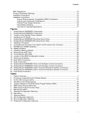
... Fan Cable to the Processor Fan Connector 24 9. PCI Configuration Submenu 44 13. RIMM Installation ...26 11. Location of the BIOS Configuration Jumper 30 15. Desktop Board D850EMD2 Add-in Card and Peripheral Interface Connectors 63 22. Installing a Memory Module 27 12. Removing the AGP Card...28 13. BIOS Setup Program Function...
... Fan Cable to the Processor Fan Connector 24 9. PCI Configuration Submenu 44 13. RIMM Installation ...26 11. Location of the BIOS Configuration Jumper 30 15. Desktop Board D850EMD2 Add-in Card and Peripheral Interface Connectors 63 22. Installing a Memory Module 27 12. Removing the AGP Card...28 13. BIOS Setup Program Function...
Product Guide
Page 7
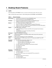
... • microATX at 9.6 inches by 9.6 inches (D850EMD2 board) • ATX at 9.6 inches by 12 inches (D850EMV2 board) • Support for an Intel® Pentium® 4 processor in card connectors • One AGP connector • One optional CNR connector continued 7 Table 1. 1 Desktop Board Features ✏ NOTE The Desktop Board D850EMD2 layout was used for up to the...routed to the back panel Two ports routed to the front panel USB connector One port routed to 2 GB of system memory Intel® 850E chipset, consisting of the Desktop Boards D850EMD2 and D850EMV2.
... • microATX at 9.6 inches by 9.6 inches (D850EMD2 board) • ATX at 9.6 inches by 12 inches (D850EMV2 board) • Support for an Intel® Pentium® 4 processor in card connectors • One AGP connector • One optional CNR connector continued 7 Table 1. 1 Desktop Board Features ✏ NOTE The Desktop Board D850EMD2 layout was used for up to the...routed to the back panel Two ports routed to the front panel USB connector One port routed to 2 GB of system memory Intel® 850E chipset, consisting of the Desktop Boards D850EMD2 and D850EMV2.
Product Guide
Page 8
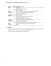
Feature Summary (continued) BIOS • Intel/AMI BIOS • 4 Mbit symmetrical flash memory • Support for SMBIOS Power Management • Support for Advanced Configuration and Power Interface (ACPI...; SCSI hard drive activity LED connector for the front panel • Speaker ✏ NOTE For information about Intel® desktop boards, including technical product specifications, BIOS updates, and device drivers, go to the Intel World Wide Web site at: http://support.intel.com/support/motherboards/desktop 8 Intel Desktop Boards D850EMD2 and D850EMV2 Product Guide Table 1.
Feature Summary (continued) BIOS • Intel/AMI BIOS • 4 Mbit symmetrical flash memory • Support for SMBIOS Power Management • Support for Advanced Configuration and Power Interface (ACPI...; SCSI hard drive activity LED connector for the front panel • Speaker ✏ NOTE For information about Intel® desktop boards, including technical product specifications, BIOS updates, and device drivers, go to the Intel World Wide Web site at: http://support.intel.com/support/motherboards/desktop 8 Intel Desktop Boards D850EMD2 and D850EMV2 Product Guide Table 1.

Product Guide
Page 10
Desktop Board D850EMV2 Components 10 A B CD E F G DD H I CC J BB K AA L Z Y X M W V TR US P Q O N OM13619 A ADI AD1885 audio codec Q Secondary IDE connector B Auxiliary line-in connector (ATAPI) R Front panel ... M RIMM fan connector (fan 1) CC Communication and Networking Riser (CNR) (optional) N Power connector DD Chassis fan connector (fan 3) O Floppy drive connector P Primary IDE connector Figure 2. Intel Desktop Boards D850EMD2 and D850EMV2 Product Guide Figure 2 shows the location of the major components on the...
Desktop Board D850EMV2 Components 10 A B CD E F G DD H I CC J BB K AA L Z Y X M W V TR US P Q O N OM13619 A ADI AD1885 audio codec Q Secondary IDE connector B Auxiliary line-in connector (ATAPI) R Front panel ... M RIMM fan connector (fan 1) CC Communication and Networking Riser (CNR) (optional) N Power connector DD Chassis fan connector (fan 3) O Floppy drive connector P Primary IDE connector Figure 2. Intel Desktop Boards D850EMD2 and D850EMV2 Product Guide Figure 2 shows the location of the major components on the...
Product Guide
Page 11
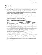
... the two power connector locations. 11 The Pentium 4 processor may result in damage to the Intel 850E chipset and Pentium 4 processor. For instructions on how to the Intel desktop board World Wide Web site at: http://support.intel.com/support/motherboards/desktop For instructions on installing or upgrading the processor, see Chapter 2 on page 60 and items...
... the two power connector locations. 11 The Pentium 4 processor may result in damage to the Intel 850E chipset and Pentium 4 processor. For instructions on how to the Intel desktop board World Wide Web site at: http://support.intel.com/support/motherboards/desktop For instructions on installing or upgrading the processor, see Chapter 2 on page 60 and items...

Product Guide
Page 12
...or 256/288 Mbit technology • Single- The desktop boards support the following devices: • Intel 82850E Memory Controller Hub (MCH) with AHA bus • Intel 82801BA I/O Controller Hub (ICH2) with AHA bus • Firmware Hub (FWH) Intel® 82850E Memory Controller Hub (MCH) The ...detection of 32 RDRAM devices per channel • 128 MB (minimum) to the Desktop Board D850EMD2 or D850EMV2 link on this Intel World Wide Web site: http://support.intel.com/support/motherboards/desktop For information about vendors that support RIMMs containing Direct Rambus DRAM (RDRAM) devices. ...
...or 256/288 Mbit technology • Single- The desktop boards support the following devices: • Intel 82850E Memory Controller Hub (MCH) with AHA bus • Intel 82801BA I/O Controller Hub (ICH2) with AHA bus • Firmware Hub (FWH) Intel® 82850E Memory Controller Hub (MCH) The ...detection of 32 RDRAM devices per channel • 128 MB (minimum) to the Desktop Board D850EMD2 or D850EMV2 link on this Intel World Wide Web site: http://support.intel.com/support/motherboards/desktop For information about vendors that support RIMMs containing Direct Rambus DRAM (RDRAM) devices. ...
Product Guide
Page 13
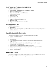
Desktop Board Features Intel® 82801BA I/O Controller Hub (ICH2) The ICH2 has these features: • Integrated Intel® Ethernet LAN MAC (external PLC required) • Support for the PCI interface • Support for the Low Pin Count (LPC) interface • ...; Intelligent power management, including a programmable wake up event interface • PCI power management support • Two fan tachometer inputs Real-Time Clock The desktop boards have a time-of-day clock and 100-year calendar. A battery on the desktop board keeps the clock current when the computer is turned off. 13
Desktop Board Features Intel® 82801BA I/O Controller Hub (ICH2) The ICH2 has these features: • Integrated Intel® Ethernet LAN MAC (external PLC required) • Support for the PCI interface • Support for the Low Pin Count (LPC) interface • ...; Intelligent power management, including a programmable wake up event interface • PCI power management support • Two fan tachometer inputs Real-Time Clock The desktop boards have a time-of-day clock and 100-year calendar. A battery on the desktop board keeps the clock current when the computer is turned off. 13

Product Guide
Page 14
...routed to the back panel, two to the front panel connector, and one to the computer without an external hub. The desktop boards support the standard universal host controller interface (UHCI) and takes advantage of information between the processor and peripheral devices like hard disks...Zip† drives inside the computer. You can connect five USB peripheral devices directly to the optional CNR. Intel Desktop Boards D850EMD2 and D850EMV2 Product Guide USB Support The desktop boards support up to either of the built-in ports. To attach additional devices, connect an external hub to...
...routed to the back panel, two to the front panel connector, and one to the computer without an external hub. The desktop boards support the standard universal host controller interface (UHCI) and takes advantage of information between the processor and peripheral devices like hard disks...Zip† drives inside the computer. You can connect five USB peripheral devices directly to the optional CNR. Intel Desktop Boards D850EMD2 and D850EMV2 Product Guide USB Support The desktop boards support up to either of the built-in ports. To attach additional devices, connect an external hub to...
Product Guide
Page 15
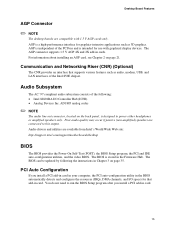
...Riser (CNR) (Optional) The CNR provides an interface that add-in card. 15 The BIOS can be updated by following : • Intel 82801BA I /O space) for use with 1.5 V AGP cards only. AGP is intended for that supports various features such as 3D graphics. ...need to this output. Desktop Board Features AGP Connector ✏ NOTE The desktop boards are compatible with graphical display devices. Poor audio quality may occur if passive (non-amplified) speakers are available from Intel's World Wide Web site: http://support.intel.com/support/motherboards/desktop BIOS The BIOS provides ...
...Riser (CNR) (Optional) The CNR provides an interface that add-in card. 15 The BIOS can be updated by following : • Intel 82801BA I /O space) for use with 1.5 V AGP cards only. AGP is intended for that supports various features such as 3D graphics. ...need to this output. Desktop Board Features AGP Connector ✏ NOTE The desktop boards are compatible with graphical display devices. Poor audio quality may occur if passive (non-amplified) speakers are available from Intel's World Wide Web site: http://support.intel.com/support/motherboards/desktop BIOS The BIOS provides ...
Product Guide
Page 16
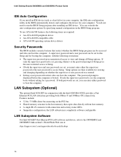
...gives unrestricted access to view and change all Setup options. If only the supervisor password is set, pressing at : http://support.intel.com/support/motherboards/desktop 16 the LAN subsystem is booted. A supervisor password and a user password can be accessed and who can boot the computer. ...subsystem providing both passwords are set, you must enter either password to run the BIOS Setup program after installing an IDE device. Intel Desktop Boards D850EMD2 and D850EMV2 Product Guide IDE Auto Configuration If you install an IDE device (such as a hard drive) in your computer,...
...gives unrestricted access to view and change all Setup options. If only the supervisor password is set, pressing at : http://support.intel.com/support/motherboards/desktop 16 the LAN subsystem is booted. A supervisor password and a user password can be accessed and who can boot the computer. ...subsystem providing both passwords are set, you must enter either password to run the BIOS Setup program after installing an IDE device. Intel Desktop Boards D850EMD2 and D850EMV2 Product Guide IDE Auto Configuration If you install an IDE device (such as a hard drive) in your computer,...
Product Guide
Page 17
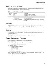
...data rate is communicating with an ACPI-aware operating system, the BIOS can provide ACPI support. The computer is selected. Battery A battery on the desktop board keeps the values in CMOS RAM and the clock current when the computer is not established. See Chapter 2 on page 21 for instructions on the... LAN. Desktop Board Features RJ-45 LAN Connector LEDs Two LEDs are built into the RJ-45 LAN connector. The speaker provides audible error code (beep code) ...
...data rate is communicating with an ACPI-aware operating system, the BIOS can provide ACPI support. The computer is selected. Battery A battery on the desktop board keeps the values in CMOS RAM and the clock current when the computer is not established. See Chapter 2 on page 21 for instructions on the... LAN. Desktop Board Features RJ-45 LAN Connector LEDs Two LEDs are built into the RJ-45 LAN connector. The speaker provides audible error code (beep code) ...

Product Guide
Page 18
...settings stored in memory. Intel Desktop Boards D850EMD2 and D850EMV2 Product Guide Instantly Available Technology CAUTION For Instantly Available technology, the 5 V standby line for the power supply must be capable of the Standby Power Indicator Power supplies used with these desktop boards must be able to ...outlined in Table 4. While in Figure 3 on the front panel, the sleep state is standby power to -RAM) sleep state. The desktop board's standby power indicator, shown in the S3 sleep state, the computer will appear to be off . CR7F1 OM13620 Figure 3. Location of providing...
...settings stored in memory. Intel Desktop Boards D850EMD2 and D850EMV2 Product Guide Instantly Available Technology CAUTION For Instantly Available technology, the 5 V standby line for the power supply must be capable of the Standby Power Indicator Power supplies used with these desktop boards must be able to ...outlined in Table 4. While in Figure 3 on the front panel, the sleep state is standby power to -RAM) sleep state. The desktop board's standby power indicator, shown in the S3 sleep state, the computer will appear to be off . CR7F1 OM13620 Figure 3. Location of providing...

Product Guide
Page 19
...non-wake enabled) USB ports** Standby Current Requirements (mA) 770* 345 375 100 875 40 700 * Refer to the Intel® Desktop Board D850EMV2/D850EMD2 Technical Product Specification for a particular system configuration, standby current requirements of all installed components must be added. Add ... total of the number of non-wake-enabled devices installed (PCI and AGP) multiplied by the standby current requirement. 5. Desktop Board Features To estimate the total amount of standby current required for the exact standby current requirements ** Dependent upon system configuration &#...
...non-wake enabled) USB ports** Standby Current Requirements (mA) 770* 345 375 100 875 40 700 * Refer to the Intel® Desktop Board D850EMV2/D850EMD2 Technical Product Specification for a particular system configuration, standby current requirements of all installed components must be added. Add ... total of the number of non-wake-enabled devices installed (PCI and AGP) multiplied by the standby current requirement. 5. Desktop Board Features To estimate the total amount of standby current required for the exact standby current requirements ** Dependent upon system configuration &#...

Product Guide
Page 20
Intel Desktop Boards D850EMD2 and D850EMV2 Product Guide Resume on Ring The operation of Resume on Ring can be summarized as follows: • Resumes operation from the ACPI S1 state • Requires only one call to access the computer • Detects incoming calls similarly for external and internal modems • Requires modem interrupt be unmasked for correct operation 20
Intel Desktop Boards D850EMD2 and D850EMV2 Product Guide Resume on Ring The operation of Resume on Ring can be summarized as follows: • Resumes operation from the ACPI S1 state • Requires only one call to access the computer • Detects incoming calls similarly for external and internal modems • Requires modem interrupt be unmasked for correct operation 20
Product Guide
Page 21
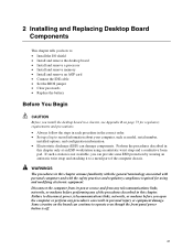
... information. • Electrostatic discharge (ESD) can damage components. 2 Installing and Replacing Desktop Board Components This chapter tells you how to: • Install the I/O shield • Install and remove the desktop board • Install and remove a processor • Install and remove memory • Install...jumper • Clear passwords • Replace the battery Before You Begin CAUTION Before you install the desktop board in a chassis, see Appendix B on the board can continue to operate even though the front panel power button is not available, you can provide ...
... information. • Electrostatic discharge (ESD) can damage components. 2 Installing and Replacing Desktop Board Components This chapter tells you how to: • Install the I/O shield • Install and remove the desktop board • Install and remove a processor • Install and remove memory • Install...jumper • Clear passwords • Replace the battery Before You Begin CAUTION Before you install the desktop board in a chassis, see Appendix B on the board can continue to operate even though the front panel power button is not available, you can provide ...

Product Guide
Page 22
... the I /O shield. Press the shield into place so that the I/O shield be done only by 11 screws. See Figure 5 and Figure 6 for instructions on this desktop board require that it fits tightly and securely. Intel Desktop Boards D850EMD2 and D850EMV2 Product Guide Installing the I/O Shield ✏ NOTE Systems based on installing and removing the...
... the I /O shield. Press the shield into place so that the I/O shield be done only by 11 screws. See Figure 5 and Figure 6 for instructions on this desktop board require that it fits tightly and securely. Intel Desktop Boards D850EMD2 and D850EMV2 Product Guide Installing the I/O Shield ✏ NOTE Systems based on installing and removing the...

Product Guide
Page 23
OM13622 Figure 6. Desktop Board D850EMV2 Mounting Screw Holes 23 Refer to Appendix B on page 73 for the Desktop Board D850EMD2. Installing and Replacing Desktop Board Components ✏ NOTES You will need a Phillips† (#2 bit) screwdriver. OM13623 Figure 5. Figure 5 shows the location of the mounting holes for the Desktop Board D850EMV2. Desktop Board D850EMD2 Mounting Screw Holes Figure 6 shows the location of the mounting holes for regulatory requirements and installation instructions and precautions.
OM13622 Figure 6. Desktop Board D850EMV2 Mounting Screw Holes 23 Refer to Appendix B on page 73 for the Desktop Board D850EMD2. Installing and Replacing Desktop Board Components ✏ NOTES You will need a Phillips† (#2 bit) screwdriver. OM13623 Figure 5. Figure 5 shows the location of the mounting holes for the Desktop Board D850EMV2. Desktop Board D850EMD2 Mounting Screw Holes Figure 6 shows the location of the mounting holes for regulatory requirements and installation instructions and precautions.


