Product Guide
Page 4
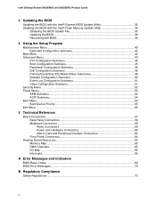
Intel Desktop Boards D850EMD2 and D850EMV2 Product Guide 3 Updating the BIOS Updating the BIOS with the Intel® Express BIOS Update Utility 35 Updating the BIOS with the Intel® Flash Memory Update Utility 35 Obtaining the BIOS Update File 35 Updating the BIOS...36 ......54 Boot Menu...55 Boot Device Priority ...55 Exit Menu ...56 5 Technical Reference Board Connectors ...57 Back Panel Connectors 58 Midboard Connectors 59 Audio Connectors 59 Power and Hardware Connectors 60 Add-In Card and Peripheral Interface Connectors 62 Front Panel Connectors 64 Desktop Board Resources...
Intel Desktop Boards D850EMD2 and D850EMV2 Product Guide 3 Updating the BIOS Updating the BIOS with the Intel® Express BIOS Update Utility 35 Updating the BIOS with the Intel® Flash Memory Update Utility 35 Obtaining the BIOS Update File 35 Updating the BIOS...36 ......54 Boot Menu...55 Boot Device Priority ...55 Exit Menu ...56 5 Technical Reference Board Connectors ...57 Back Panel Connectors 58 Midboard Connectors 59 Audio Connectors 59 Power and Hardware Connectors 60 Add-In Card and Peripheral Interface Connectors 62 Front Panel Connectors 64 Desktop Board Resources...
Product Guide
Page 5
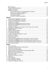
... the Battery...34 16. Desktop Board D850EMV2 Power and Hardware Control Connectors 61 20. Desktop Board D850EMD2 Add-in Card and Peripheral Interface Connectors 63 22. Main Menu ...42 11. Desktop Board D850EMD2 Mounting Screw Holes 23 6. Installing a Processor...24 8. Desktop Board D850EMD2 Power and Hardware Control Connectors 60 19. Advanced Menu ...43 12. Boot Configuration Submenu 45 14. Installing...
... the Battery...34 16. Desktop Board D850EMV2 Power and Hardware Control Connectors 61 20. Desktop Board D850EMD2 Add-in Card and Peripheral Interface Connectors 63 22. Main Menu ...42 11. Desktop Board D850EMD2 Mounting Screw Holes 23 6. Installing a Processor...24 8. Desktop Board D850EMD2 Power and Hardware Control Connectors 60 19. Advanced Menu ...43 12. Boot Configuration Submenu 45 14. Installing...
Product Guide
Page 16
...If both passwords are set, you can override the auto-configuration options by specifying manual configuration in the BIOS Setup program. Intel Desktop Boards D850EMD2 and D850EMV2 Product Guide IDE Auto Configuration If you install an IDE device (such as a hard drive) in your computer, the ... and 100Base-TX connectivity. If only the supervisor password is set , pressing at : http://support.intel.com/support/motherboards/desktop 16 If only the supervisor password is set , the computer boots without asking for your computer. Features include: • 32-bit, 33-MHz direct bus mastering on...
...If both passwords are set, you can override the auto-configuration options by specifying manual configuration in the BIOS Setup program. Intel Desktop Boards D850EMD2 and D850EMV2 Product Guide IDE Auto Configuration If you install an IDE device (such as a hard drive) in your computer, the ... and 100Base-TX connectivity. If only the supervisor password is set , pressing at : http://support.intel.com/support/motherboards/desktop 16 If only the supervisor password is set , the computer boots without asking for your computer. Features include: • 32-bit, 33-MHz direct bus mastering on...
Product Guide
Page 25
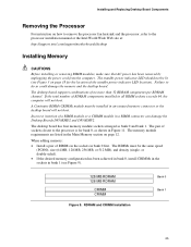
...of RIMMs in the sockets in a RIMM connector can damage the Desktop Boards D850EMD2 and D850EMV2. The memory module requirements are listed in Figure 11. The RIMMs...install CRIMMs in the sockets in any unused memory connector or the desktop board will not boot. Incorrect insertion of no more than 32 RDRAM components per RDRAM ...Intel World Wide Web site at: http://support.intel.com/support/motherboards/desktop Installing Memory CAUTIONS Before installing or removing RIMM modules, make sure that AC power has been removed by unplugging the power cord from the computer. The desktop board...
...of RIMMs in the sockets in a RIMM connector can damage the Desktop Boards D850EMD2 and D850EMV2. The memory module requirements are listed in Figure 11. The RIMMs...install CRIMMs in the sockets in any unused memory connector or the desktop board will not boot. Incorrect insertion of no more than 32 RDRAM components per RDRAM ...Intel World Wide Web site at: http://support.intel.com/support/motherboards/desktop Installing Memory CAUTIONS Before installing or removing RIMM modules, make sure that AC power has been removed by unplugging the power cord from the computer. The desktop board...
Product Guide
Page 30
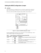
... to be done in unreliable computer operation. Table 5 shows the jumper settings for booting. Use this menu to recover the BIOS configuration. Moving the jumper with the power on may result in BIOS Setup. Table 5. Intel Desktop Boards D850EMD2 and D850EMV2 Product Guide Setting the BIOS Configuration Jumper CAUTION Always turn off the power and...
... to be done in unreliable computer operation. Table 5 shows the jumper settings for booting. Use this menu to recover the BIOS configuration. Moving the jumper with the power on may result in BIOS Setup. Table 5. Intel Desktop Boards D850EMD2 and D850EMV2 Product Guide Setting the BIOS Configuration Jumper CAUTION Always turn off the power and...
Product Guide
Page 36
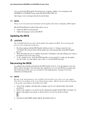
... page 30 for the Setup program. Monitor the procedure by navigating to the D850EMD2 or D850EMV2 page on the Intel World Wide Web site: http://support.intel.com/support/motherboards/desktop ✏ NOTE Please review the instructions distributed with the update files updates the BIOS. Insert...appears, press to : • Update the BIOS in the boot block area, there is complete, the monitor will automatically run the BIOS update process. 2. You will interrupt the BIOS update; Intel Desktop Boards D850EMD2 and D850EMV2 Product Guide You can obtain the BIOS update file through your ...
... page 30 for the Setup program. Monitor the procedure by navigating to the D850EMD2 or D850EMV2 page on the Intel World Wide Web site: http://support.intel.com/support/motherboards/desktop ✏ NOTE Please review the instructions distributed with the update files updates the BIOS. Insert...appears, press to : • Update the BIOS in the boot block area, there is complete, the monitor will automatically run the BIOS update process. 2. You will interrupt the BIOS update; Intel Desktop Boards D850EMD2 and D850EMV2 Product Guide You can obtain the BIOS update file through your ...

Product Guide
Page 39
... show the latest settings. For the latest BIOS settings, refer to the Intel Desktop Board D850EMD2/D850EMV2 Technical Product Specification or the Intel World Wide Web site: http://support.intel.com/support/motherboards/desktop ✏ NOTE For reference purposes, you make changes to the settings, ... the current Setup settings. Maintenance Main Advanced Security Power Boot Exit Table 6 shows the BIOS Setup program menu bar. BIOS Setup Program Menu Bar Maintenance Clears passwords and Boot Integrity Service (BIS)* credentials, and configures extended configuration memory...
... show the latest settings. For the latest BIOS settings, refer to the Intel Desktop Board D850EMD2/D850EMV2 Technical Product Specification or the Intel World Wide Web site: http://support.intel.com/support/motherboards/desktop ✏ NOTE For reference purposes, you make changes to the settings, ... the current Setup settings. Maintenance Main Advanced Security Power Boot Exit Table 6 shows the BIOS Setup program menu bar. BIOS Setup Program Menu Bar Maintenance Clears passwords and Boot Integrity Service (BIS)* credentials, and configures extended configuration memory...

Product Guide
Page 40
... Save the current values and exits the BIOS Setup program Exits the menu Maintenance Menu Maintenance Main Advanced Security Power Boot Exit The menu shown in configure mode. Invokes the Extended Configuration submenu. Displays the processor's microcode update revision. ... enable extended configuration mode. Clears the Wired for menu screens. Displays processor information. Intel Desktop Boards D850EMD2 and D850EMV2 Product Guide Table 7 shows the function keys available for Management Boot Integrity Service (BIS) credentials. Setup only displays this menu in Table 8 is ...
... Save the current values and exits the BIOS Setup program Exits the menu Maintenance Menu Maintenance Main Advanced Security Power Boot Exit The menu shown in configure mode. Invokes the Extended Configuration submenu. Displays the processor's microcode update revision. ... enable extended configuration mode. Clears the Wired for menu screens. Displays processor information. Intel Desktop Boards D850EMD2 and D850EMV2 Product Guide Table 7 shows the function keys available for Management Boot Integrity Service (BIS) credentials. Setup only displays this menu in Table 8 is ...
Product Guide
Page 42
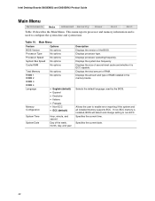
... type of second-level cache and whether it is ECC-capable. Displays processor operating frequency. Displays the size of RAM installed in the memory banks. Intel Desktop Boards D850EMD2 and D850EMV2 Product Guide Main Menu Maintenance Main Advanced Security Power Boot Exit Table 10 describes the Main Menu. Table 10. Displays processor type.
... type of second-level cache and whether it is ECC-capable. Displays processor operating frequency. Displays the size of RAM installed in the memory banks. Intel Desktop Boards D850EMD2 and D850EMV2 Product Guide Main Menu Maintenance Main Advanced Security Power Boot Exit Table 10 describes the Main Menu. Table 10. Displays processor type.

Product Guide
Page 44
...; 9 • 10 • 11 No options Description Allows selection of IRQ priority. Intel Desktop Boards D850EMD2 and D850EMV2 Product Guide PCI Configuration Submenu Maintenance Main Advanced Security Power PCI Configuration Boot Configuration Peripheral Configuration IDE Configuration Diskette Configuration Event Log Configuration Video Configuration Boot Exit The submenu shown in PCI Slot 5 IRQ Priority. IRQ Priority selections...
...; 9 • 10 • 11 No options Description Allows selection of IRQ priority. Intel Desktop Boards D850EMD2 and D850EMV2 Product Guide PCI Configuration Submenu Maintenance Main Advanced Security Power PCI Configuration Boot Configuration Peripheral Configuration IDE Configuration Diskette Configuration Event Log Configuration Video Configuration Boot Exit The submenu shown in PCI Slot 5 IRQ Priority. IRQ Priority selections...

Product Guide
Page 46
... port, normally COM 2, the address 3F8h, and the interrupt IRQ4. continued 46 Intel Desktop Boards D850EMD2 and D850EMV2 Product Guide Peripheral Configuration Submenu Maintenance Main Advanced Security Power PCI Configuration Boot Configuration Peripheral Configuration IDE Configuration Diskette Configuration Event Log Configuration Video Configuration Boot Exit This submenu shown in Table 14 is used to an address...
... port, normally COM 2, the address 3F8h, and the interrupt IRQ4. continued 46 Intel Desktop Boards D850EMD2 and D850EMV2 Product Guide Peripheral Configuration Submenu Maintenance Main Advanced Security Power PCI Configuration Boot Configuration Peripheral Configuration IDE Configuration Diskette Configuration Event Log Configuration Video Configuration Boot Exit This submenu shown in Table 14 is used to an address...

Product Guide
Page 48
... the primary IDE controller. When selected, displays the Primary IDE Slave submenu. Intel Desktop Boards D850EMD2 and D850EMV2 Product Guide IDE Configuration Submenu Maintenance Main Advanced Security Power PCI Configuration Boot Configuration Peripheral Configuration IDE Configuration Diskette Configuration Event Log Configuration Video Configuration Boot This submenu shown in Table 15 is used to configure IDE device...
... the primary IDE controller. When selected, displays the Primary IDE Slave submenu. Intel Desktop Boards D850EMD2 and D850EMV2 Product Guide IDE Configuration Submenu Maintenance Main Advanced Security Power PCI Configuration Boot Configuration Peripheral Configuration IDE Configuration Diskette Configuration Event Log Configuration Video Configuration Boot This submenu shown in Table 15 is used to configure IDE device...
Product Guide
Page 50
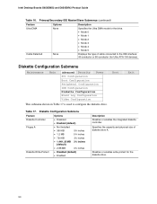
...• Mode 1 • Mode 2 • Mode 3 • Mode 4 • Mode 5 Displays the type of diskette drive A. Boot Exit Table 17. Diskette Configuration Submenu Feature Diskette Controller Floppy A Diskette Write-Protect Options • Disabled • Enabled (default) • Not ...Boot Configuration Peripheral Configuration IDE Configuration Diskette Configuration Event Log Configuration Video Configuration This submenu shown in Table 17 is used to the IDE interface: 40-conductor or 80-conductor (for the diskette drive. 50 Intel Desktop Boards D850EMD2 and D850EMV2...
...• Mode 1 • Mode 2 • Mode 3 • Mode 4 • Mode 5 Displays the type of diskette drive A. Boot Exit Table 17. Diskette Configuration Submenu Feature Diskette Controller Floppy A Diskette Write-Protect Options • Disabled • Enabled (default) • Not ...Boot Configuration Peripheral Configuration IDE Configuration Diskette Configuration Event Log Configuration Video Configuration This submenu shown in Table 17 is used to the IDE interface: 40-conductor or 80-conductor (for the diskette drive. 50 Intel Desktop Boards D850EMD2 and D850EMV2...

Product Guide
Page 52
... level. • View Only • Full (default) • Enabled • Disabled (default) Enabled allows system to seven Specifies the user password. Intel Desktop Boards D850EMD2 and D850EMV2 Product Guide Security Menu Maintenance Main Advanced Security Power Boot The menu shown in Table 20 is entered. Notes: 1. The keyboard remains locked until a password is used to...
... level. • View Only • Full (default) • Enabled • Disabled (default) Enabled allows system to seven Specifies the user password. Intel Desktop Boards D850EMD2 and D850EMV2 Product Guide Security Menu Maintenance Main Advanced Security Power Boot The menu shown in Table 20 is entered. Notes: 1. The keyboard remains locked until a password is used to...
Product Guide
Page 54
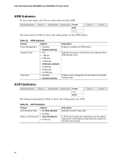
... Exit Table 22. Intel Desktop Boards D850EMD2 and D850EMV2 Product Guide APM Submenu To access this menu, select Power on LAN from S5 • S1 State (default) • S3 State • Stay Off (default) • Power On Description Specifies the ACPI sleep state. Maintenance Main Advanced Security Power APM ACPI Boot The menu shown in...
... Exit Table 22. Intel Desktop Boards D850EMD2 and D850EMV2 Product Guide APM Submenu To access this menu, select Power on LAN from S5 • S1 State (default) • S3 State • Stay Off (default) • Power On Description Specifies the ACPI sleep state. Maintenance Main Advanced Security Power APM ACPI Boot The menu shown in...

Product Guide
Page 56
... without saving any changes made in the BIOS Setup program. Load Custom Defaults Loads the custom defaults for all the Setup options. Intel Desktop Boards D850EMD2 and D850EMV2 Product Guide Exit Menu Maintenance Main Advanced Security Power Boot Exit The menu shown in Table 26 is corrupted, the BIOS reads the custom defaults. Table 26.
... without saving any changes made in the BIOS Setup program. Load Custom Defaults Loads the custom defaults for all the Setup options. Intel Desktop Boards D850EMD2 and D850EMV2 Product Guide Exit Menu Maintenance Main Advanced Security Power Boot Exit The menu shown in Table 26 is corrupted, the BIOS reads the custom defaults. Table 26.
Product Guide
Page 70
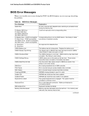
... has been updated. continued 70 CMOS Battery Low The battery may have either been corrupted or the battery has failed. Intel Desktop Boards D850EMD2 and D850EMV2 Product Guide BIOS Error Messages When a recoverable error occurs during read sector from diskette drive. Pri Master HDD Error Pri...The system must be losing power. BIOS Error Messages Error Message Explanation GA20 Error An error occurred with GateA20 when switching to boot. CMOS Checksum Bad The CMOS checksum is different than what has been stored in CMOS. CMOS Display Type Wrong The display type...
... has been updated. continued 70 CMOS Battery Low The battery may have either been corrupted or the battery has failed. Intel Desktop Boards D850EMD2 and D850EMV2 Product Guide BIOS Error Messages When a recoverable error occurs during read sector from diskette drive. Pri Master HDD Error Pri...The system must be losing power. BIOS Error Messages Error Message Explanation GA20 Error An error occurred with GateA20 when switching to boot. CMOS Checksum Bad The CMOS checksum is different than what has been stored in CMOS. CMOS Display Type Wrong The display type...


