Product Guide
Page 4
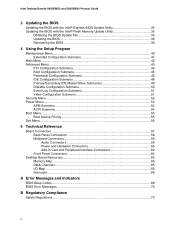
Intel Desktop Boards D850EMD2 and D850EMV2 Product Guide 3 Updating the BIOS Updating the BIOS with the Intel® Express BIOS Update Utility 35 Updating the BIOS with the Intel® Flash Memory Update Utility 35 Obtaining the BIOS Update File 35 Updating the BIOS...36 Recovering the ... 58 Midboard Connectors 59 Audio Connectors 59 Power and Hardware Connectors 60 Add-In Card and Peripheral Interface Connectors 62 Front Panel Connectors 64 Desktop Board Resources 65 Memory Map ...65 DMA Channels ...65 I/O Map ...66 Interrupts ...68 A Error Messages and Indicators BIOS Beep Codes ...
Intel Desktop Boards D850EMD2 and D850EMV2 Product Guide 3 Updating the BIOS Updating the BIOS with the Intel® Express BIOS Update Utility 35 Updating the BIOS with the Intel® Flash Memory Update Utility 35 Obtaining the BIOS Update File 35 Updating the BIOS...36 Recovering the ... 58 Midboard Connectors 59 Audio Connectors 59 Power and Hardware Connectors 60 Add-In Card and Peripheral Interface Connectors 62 Front Panel Connectors 64 Desktop Board Resources 65 Memory Map ...65 DMA Channels ...65 I/O Map ...66 Interrupts ...68 A Error Messages and Indicators BIOS Beep Codes ...
Product Guide
Page 5
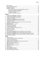
... 76 Place Battery Marking 76 Use Only for the BIOS Setup Program Modes (J9H2 30 6. Desktop Board D850EMD2 Components 9 2. Installing a Processor...24 8. Desktop Board D850EMV2 Power and Hardware Control Connectors 61 20. Feature Summary ...7 2. Standby Current Requirements 19 5. ... Main Menu ...42 11. Desktop Board D850EMV2 Mounting Screw Holes 23 7. BIOS Setup Program Menu Bar 39 7. Peripheral Configuration Submenu 46 v Installing the I/O Shield ...22 5. Removing the AGP Card...28 13. Back Panel Connectors...58 17. Desktop Board D850EMD2 Power and Hardware Control...
... 76 Place Battery Marking 76 Use Only for the BIOS Setup Program Modes (J9H2 30 6. Desktop Board D850EMD2 Components 9 2. Installing a Processor...24 8. Desktop Board D850EMV2 Power and Hardware Control Connectors 61 20. Feature Summary ...7 2. Standby Current Requirements 19 5. ... Main Menu ...42 11. Desktop Board D850EMV2 Mounting Screw Holes 23 7. BIOS Setup Program Menu Bar 39 7. Peripheral Configuration Submenu 46 v Installing the I/O Shield ...22 5. Removing the AGP Card...28 13. Back Panel Connectors...58 17. Desktop Board D850EMD2 Power and Hardware Control...
Product Guide
Page 7
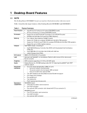
...continued 7 Feature Summary Form Factors Processor Memory Chipset • microATX at 9.6 inches by 9.6 inches (D850EMD2 board) • ATX at 9.6 inches by 12 inches (D850EMV2 board) • Support for an Intel® Pentium® 4 processor in an mPGA478 socket • 533 MHz and 400 MHz front side... Up to five Universal Serial Bus (USB) 2.0 ports Two ports routed to the back panel Two ports routed to the front panel USB connector One port routed to 2 GB of system memory Intel® 850E chipset, consisting of the Desktop Boards D850EMD2 and D850EMV2.
...continued 7 Feature Summary Form Factors Processor Memory Chipset • microATX at 9.6 inches by 9.6 inches (D850EMD2 board) • ATX at 9.6 inches by 12 inches (D850EMV2 board) • Support for an Intel® Pentium® 4 processor in an mPGA478 socket • 533 MHz and 400 MHz front side... Up to five Universal Serial Bus (USB) 2.0 ports Two ports routed to the back panel Two ports routed to the front panel USB connector One port routed to 2 GB of system memory Intel® 850E chipset, consisting of the Desktop Boards D850EMD2 and D850EMV2.
Product Guide
Page 8
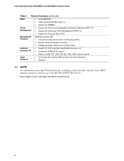
Feature Summary (continued) BIOS • Intel/AMI BIOS • 4 Mbit symmetrical flash memory • Support for SMBIOS Power Management • Support for Advanced Configuration and ... front panel Other Features • SCSI hard drive activity LED connector for the front panel • Speaker ✏ NOTE For information about Intel® desktop boards, including technical product specifications, BIOS updates, and device drivers, go to the Intel World Wide Web site at: http://support.intel.com/support/motherboards/desktop 8 Intel Desktop Boards D850EMD2 and D850EMV2 Product...
Feature Summary (continued) BIOS • Intel/AMI BIOS • 4 Mbit symmetrical flash memory • Support for SMBIOS Power Management • Support for Advanced Configuration and ... front panel Other Features • SCSI hard drive activity LED connector for the front panel • Speaker ✏ NOTE For information about Intel® desktop boards, including technical product specifications, BIOS updates, and device drivers, go to the Intel World Wide Web site at: http://support.intel.com/support/motherboards/desktop 8 Intel Desktop Boards D850EMD2 and D850EMV2 Product...

Product Guide
Page 10
... AGP connector S Alternate power/sleep LED connector D CD-ROM connector (ATAPI) T Front panel connector E Front panel audio connector U Chassis fan connector (fan 2) (tachometer input) F Chassis intrusion connector V Battery G Back panel connectors W Speaker H ATX12V processor core voltage connector X BIOS configuration jumper I Processor fan connector...) N Power connector DD Chassis fan connector (fan 3) O Floppy drive connector P Primary IDE connector Figure 2. Intel Desktop Boards D850EMD2 and D850EMV2 Product Guide Figure 2 shows the location of the major components on the...
... AGP connector S Alternate power/sleep LED connector D CD-ROM connector (ATAPI) T Front panel connector E Front panel audio connector U Chassis fan connector (fan 2) (tachometer input) F Chassis intrusion connector V Battery G Back panel connectors W Speaker H ATX12V processor core voltage connector X BIOS configuration jumper I Processor fan connector...) N Power connector DD Chassis fan connector (fan 3) O Floppy drive connector P Primary IDE connector Figure 2. Intel Desktop Boards D850EMD2 and D850EMV2 Product Guide Figure 2 shows the location of the major components on the...

Product Guide
Page 14
...devices, connect an external hub to the cable. The desktop boards support the standard universal host controller interface (UHCI) and takes advantage of standard software drivers written to be compatible with PCI bus connector 3) The D850EMV2 board has: • Five PCI bus add-in card ... interface supports: • Up to the computer without an external hub. Intel Desktop Boards D850EMD2 and D850EMV2 Product Guide USB Support The desktop boards support up to the optional CNR. two ports routed to the back panel, two to the front panel connector, and one to five USB 2.0 ports;
...devices, connect an external hub to the cable. The desktop boards support the standard universal host controller interface (UHCI) and takes advantage of standard software drivers written to be compatible with PCI bus connector 3) The D850EMV2 board has: • Five PCI bus add-in card ... interface supports: • Up to the computer without an external hub. Intel Desktop Boards D850EMD2 and D850EMV2 Product Guide USB Support The desktop boards support up to the optional CNR. two ports routed to the back panel, two to the front panel connector, and one to five USB 2.0 ports;

Product Guide
Page 18
...ACPI S3 sleep state functionality. The desktop board's standby power indicator, shown in ...technology enables the desktop board to enter the ACPI S3 (Suspend-to be off . Intel Desktop Boards D850EMD2 and D850EMV2 Product Guide Instantly ...Available Technology CAUTION For Instantly Available technology, the 5 V standby line for the power supply must be capable of the Standby Power Indicator Power supplies used with these desktop boards...buses exceeds power supply capacity, the desktop board may vary. 18 CR7F1 OM13620 Figure...
...ACPI S3 sleep state functionality. The desktop board's standby power indicator, shown in ...technology enables the desktop board to enter the ACPI S3 (Suspend-to be off . Intel Desktop Boards D850EMD2 and D850EMV2 Product Guide Instantly ...Available Technology CAUTION For Instantly Available technology, the 5 V standby line for the power supply must be capable of the Standby Power Indicator Power supplies used with these desktop boards...buses exceeds power supply capacity, the desktop board may vary. 18 CR7F1 OM13620 Figure...

Product Guide
Page 28
...the card's metal bracket (A) to the chassis back panel with a screw. Push back on the card until the retention pin (C) completely clears the notch in the AGP connector. 2. B E A C D Figure 12. Intel Desktop Boards D850EMD2 and D850EMV2 Product Guide Installing an AGP Card The AGP connector ...supports 1.5 V 4X and 2X AGP cards. The desktop board has an integrated AGP retention mechanism (RM). Removing the AGP Card Follow these...
...the card's metal bracket (A) to the chassis back panel with a screw. Push back on the card until the retention pin (C) completely clears the notch in the AGP connector. 2. B E A C D Figure 12. Intel Desktop Boards D850EMD2 and D850EMV2 Product Guide Installing an AGP Card The AGP connector ...supports 1.5 V 4X and 2X AGP cards. The desktop board has an integrated AGP retention mechanism (RM). Removing the AGP Card Follow these...

Product Guide
Page 58
... Color Green Purple Burgundy Teal Teal Black Black Black Pink Lime green Light blue OM13629 Figure 16. Intel Desktop Boards D850EMD2 and D850EMV2 Product Guide Back Panel Connectors Figure 16 shows the back panel connectors on the back panel, is designed to this output. 58 Poor audio quality may occur if passive (non-amplified) speakers are connected...
... Color Green Purple Burgundy Teal Teal Black Black Black Pink Lime green Light blue OM13629 Figure 16. Intel Desktop Boards D850EMD2 and D850EMV2 Product Guide Back Panel Connectors Figure 16 shows the back panel connectors on the back panel, is designed to this output. 58 Poor audio quality may occur if passive (non-amplified) speakers are connected...

Product Guide
Page 64
Intel Desktop Boards D850EMD2 and D850EMV2 Product Guide Front Panel Connectors Figure 22 shows the location of the front panel connectors on the desktop boards. 1 A B C 1 12 10 7 HD LED 1 2 Power LED Reset On No Connection 15 16 Item A B C Ground +5V Description Front panel audio Front panel USB 2.0 Alternate power/sleep LED Figure 22. Front Panel Connectors OM14564 64
Intel Desktop Boards D850EMD2 and D850EMV2 Product Guide Front Panel Connectors Figure 22 shows the location of the front panel connectors on the desktop boards. 1 A B C 1 12 10 7 HD LED 1 2 Power LED Reset On No Connection 15 16 Item A B C Ground +5V Description Front panel audio Front panel USB 2.0 Alternate power/sleep LED Figure 22. Front Panel Connectors OM14564 64


