
Product Guide
Page 5
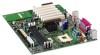
... DMA Channels ...74 I /O Shield 22 5. Installing the I /O Map ...75 Interrupts ...77 A Error Messages and Indicators BIOS Beep Codes ...79 BIOS Error Messages ...80 B Regulatory Compliance Safety Regulations ...83 EMC Regulations ...83 Product Certification Markings 84 Installation Precautions ...85 ...Removing the AGP Card Retention Mechanism 35 16. Location of Standby Power Indicator 18 4. D845WN Board Components 10 3. Location of the BIOS Configuration Jumper Block 37 18. D845WN Board Mounting Holes 24 7. Removing the Battery 41 19. Audio Connectors ...69 v ...
... DMA Channels ...74 I /O Shield 22 5. Installing the I /O Map ...75 Interrupts ...77 A Error Messages and Indicators BIOS Beep Codes ...79 BIOS Error Messages ...80 B Regulatory Compliance Safety Regulations ...83 EMC Regulations ...83 Product Certification Markings 84 Installation Precautions ...85 ...Removing the AGP Card Retention Mechanism 35 16. Location of Standby Power Indicator 18 4. D845WN Board Components 10 3. Location of the BIOS Configuration Jumper Block 37 18. D845WN Board Mounting Holes 24 7. Removing the Battery 41 19. Audio Connectors ...69 v ...

Product Guide
Page 6
...in Card and Peripheral Interface Connectors 72 24. Standby Current Requirements 19 5. PCI Configuration Submenu 52 13. Security Menu...61 21. Beep Codes ...79 34. Safety Regulations...83 36. Extended Configuration Submenu 49 10. Boot Configuration Submenu 53 14. Diskette Configuration Submenu 58 18...-45 LAN Connector LEDs 17 4. BIOS Setup Program Menu Bar 47 7. Main Menu...50 11. EMC Regulations ...83 vi Intel Desktop Boards D845HV and D845WN Product Guide 21. Jumper Settings for the BIOS Setup Program Modes (J9G1 37 6. Advanced Menu...51 12. Primary/Secondary IDE...
...in Card and Peripheral Interface Connectors 72 24. Standby Current Requirements 19 5. PCI Configuration Submenu 52 13. Security Menu...61 21. Beep Codes ...79 34. Safety Regulations...83 36. Extended Configuration Submenu 49 10. Boot Configuration Submenu 53 14. Diskette Configuration Submenu 58 18...-45 LAN Connector LEDs 17 4. BIOS Setup Program Menu Bar 47 7. Main Menu...50 11. EMC Regulations ...83 vi Intel Desktop Boards D845HV and D845WN Product Guide 21. Jumper Settings for the BIOS Setup Program Modes (J9G1 37 6. Advanced Menu...51 12. Primary/Secondary IDE...
Product Guide
Page 17
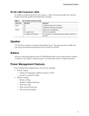
On 100 Mbit/sec data rate is mounted on the desktop board. The speaker provides audible error code (beep code) information during the Power-On Self-Test (POST). Speaker A 47 Ω inductive speaker is selected. Desktop Board Features RJ-45 LAN Connector LEDs Two LEDs ...
On 100 Mbit/sec data rate is mounted on the desktop board. The speaker provides audible error code (beep code) information during the Power-On Self-Test (POST). Speaker A 47 Ω inductive speaker is selected. Desktop Board Features RJ-45 LAN Connector LEDs Two LEDs ...
Product Guide
Page 45
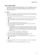
...The following steps. 10. You will take a few minutes. 6. In about a minute, two beeps are heard and drive A activity ceases (temporarily) indicating the successful recovery of continuous beeps indicates a failed BIOS recovery. 7. Updating the BIOS Recovering the BIOS It is no video support...diskette into diskette drive A. 5. Turn on the computer and continue with the following procedure uses recovery mode for more beeps indicating the successful recovery of code available in drive A, replace the computer cover, and connect the computer's power cord. 12. If recovery fails,...
...The following steps. 10. You will take a few minutes. 6. In about a minute, two beeps are heard and drive A activity ceases (temporarily) indicating the successful recovery of continuous beeps indicates a failed BIOS recovery. 7. Updating the BIOS Recovering the BIOS It is no video support...diskette into diskette drive A. 5. Turn on the computer and continue with the following procedure uses recovery mode for more beeps indicating the successful recovery of code available in drive A, replace the computer cover, and connect the computer's power cord. 12. If recovery fails,...

Product Guide
Page 79
The BIOS also issues a beep code (one long tone followed by two short tones) during POST if the video configuration fails (a faulty video card or no card installed) or if an ... Beep Codes Number of Beeps Description 1 Refresh failure 2 Parity cannot be toggled (memory failure or not present) 7 Exception interrupt error 8 Display memory R/W error 9 (Reserved; A Error Messages and Indicators The D845HV and D845WN boards report POST errors in two ways: • By sounding a beep code • By displaying an error message on the monitor BIOS Beep Codes The BIOS beep codes...
The BIOS also issues a beep code (one long tone followed by two short tones) during POST if the video configuration fails (a faulty video card or no card installed) or if an ... Beep Codes Number of Beeps Description 1 Refresh failure 2 Parity cannot be toggled (memory failure or not present) 7 Exception interrupt error 8 Display memory R/W error 9 (Reserved; A Error Messages and Indicators The D845HV and D845WN boards report POST errors in two ways: • By sounding a beep code • By displaying an error message on the monitor BIOS Beep Codes The BIOS beep codes...


