Product Guide
Page 3
...Support 15 Enhanced IDE Interface ...16 Expansion Slots...16 Accelerated Graphics Port (AGP 16 Communication and Networking Riser (CNR) (Optional 16 BIOS ...17 PCI Auto Configuration 17 IDE Auto Configuration 17 Security Passwords ...17 Power Management Features 17 ACPI ...18 Suspend to RAM (Instantly... ...19 Fan Speed Control (Intel® Precision Cooling Technology 19 Resume on Ring...20 Wake from USB...20 Wake from PS/2 Keyboard/Mouse 20 PME# Wakeup Support 20 Speaker...20 Battery...20 Real-Time Clock...20 2 Installing and Replacing Desktop Board Components Before You Begin ...21...
...Support 15 Enhanced IDE Interface ...16 Expansion Slots...16 Accelerated Graphics Port (AGP 16 Communication and Networking Riser (CNR) (Optional 16 BIOS ...17 PCI Auto Configuration 17 IDE Auto Configuration 17 Security Passwords ...17 Power Management Features 17 ACPI ...18 Suspend to RAM (Instantly... ...19 Fan Speed Control (Intel® Precision Cooling Technology 19 Resume on Ring...20 Wake from USB...20 Wake from PS/2 Keyboard/Mouse 20 PME# Wakeup Support 20 Speaker...20 Battery...20 Real-Time Clock...20 2 Installing and Replacing Desktop Board Components Before You Begin ...21...
Product Guide
Page 4
Intel Desktop Boards D845GERG2 and D845GEBV2 Product Guide Installing a Processor 24 Installing the Processor Fan Heat Sink 24 Connecting the Processor Fan Heat Sink Cable 25 Removing the Processor 25 Installing ... Clearing Passwords ...35 Replacing the Battery ...36 3 Updating the BIOS Updating the BIOS with the Intel® Express BIOS Update Utility 39 Updating the BIOS with the Intel® Flash Memory Update Utility 40 Obtaining the BIOS Update File 40 Updating the BIOS...40 Recovering the BIOS 41 4 Using the BIOS Setup Program Maintenance Menu...44 Main Menu ...45 Advanced...
Intel Desktop Boards D845GERG2 and D845GEBV2 Product Guide Installing a Processor 24 Installing the Processor Fan Heat Sink 24 Connecting the Processor Fan Heat Sink Cable 25 Removing the Processor 25 Installing ... Clearing Passwords ...35 Replacing the Battery ...36 3 Updating the BIOS Updating the BIOS with the Intel® Express BIOS Update Utility 39 Updating the BIOS with the Intel® Flash Memory Update Utility 40 Obtaining the BIOS Update File 40 Updating the BIOS...40 Recovering the BIOS 41 4 Using the BIOS Setup Program Maintenance Menu...44 Main Menu ...45 Advanced...
Product Guide
Page 5
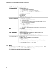
Desktop Board D845GEBV2 Components 10 3. Location of the BIOS Configuration Jumper Block 34 14. Connecting the Processor Fan Heat Sink Cable to the Processor Fan Connector ........25 8. Location of Standby Power Indicator 18 4. Removing the AGP or ADD Card 28 10. Location of Desktop Board Mounting Holes 23 6. Installing a Processor...24 7. Desktop Board...Card and Peripheral Interface Connectors 66 Desktop Board Resources 67 Memory Map ...67 DMA Channels ...67 Interrupts ...68 A Error Messages and Indicators BIOS Beep Codes ...69 BIOS Error Messages ...70 B Regulatory ...
Desktop Board D845GEBV2 Components 10 3. Location of the BIOS Configuration Jumper Block 34 14. Connecting the Processor Fan Heat Sink Cable to the Processor Fan Connector ........25 8. Location of Standby Power Indicator 18 4. Removing the AGP or ADD Card 28 10. Location of Desktop Board Mounting Holes 23 6. Installing a Processor...24 7. Desktop Board...Card and Peripheral Interface Connectors 66 Desktop Board Resources 67 Memory Map ...67 DMA Channels ...67 Interrupts ...68 A Error Messages and Indicators BIOS Beep Codes ...69 BIOS Error Messages ...70 B Regulatory ...
Product Guide
Page 6
... Hard Disk Drives Submenu 59 31. System Memory Map...67 35. BIOS Error Messages 70 39. Back Panel Connectors 64 16. Audio Connectors ...65 17. Jumper Settings for the BIOS Setup Program Modes (J9H2 34 9. BIOS Setup Program Menu Bar 43 10. Maintenance Menu ...44 12. Boot ... 2.0 Header (J9F1 32 8. Boot Device Priority Submenu 59 30. Feature Summary ...7 2. Front Panel Audio Header Signal Names (J8A1 31 7. BIOS Setup Program Function Keys 44 11. Beep Codes ...69 38. Main Menu...45 13. Exit Menu...61 34. Intel Desktop Boards D845GERG2 and D845GEBV2 Product Guide 15.
... Hard Disk Drives Submenu 59 31. System Memory Map...67 35. BIOS Error Messages 70 39. Back Panel Connectors 64 16. Audio Connectors ...65 17. Jumper Settings for the BIOS Setup Program Modes (J9H2 34 9. BIOS Setup Program Menu Bar 43 10. Maintenance Menu ...44 12. Boot ... 2.0 Header (J9F1 32 8. Boot Device Priority Submenu 59 30. Feature Summary ...7 2. Front Panel Audio Header Signal Names (J8A1 31 7. BIOS Setup Program Function Keys 44 11. Beep Codes ...69 38. Main Menu...45 13. Exit Menu...61 34. Intel Desktop Boards D845GERG2 and D845GEBV2 Product Guide 15.
Product Guide
Page 8
... at: http://support.intel.com/support/motherboards/desktop/ 8 Six PCI bus add-in card connectors - One AGP connector - One AGP connector One optional CNR connector (slot shared with PCI bus connector 6) BIOS • Intel/AMI BIOS • 4 Mbit...Capabilities • Desktop Board D845GERG2: - One optional Communication and Networking Riser (CNR) connector (slot shared with PCI bus connector 3) • Desktop Board D845GEBV2: - Three PCI bus add-in card connectors - Four ports routed to six USB 2.0 ports - Intel Desktop Board D845GERG2/D845GEBV2 Product Guide ...
... at: http://support.intel.com/support/motherboards/desktop/ 8 Six PCI bus add-in card connectors - One AGP connector - One AGP connector One optional CNR connector (slot shared with PCI bus connector 6) BIOS • Intel/AMI BIOS • 4 Mbit...Capabilities • Desktop Board D845GERG2: - One optional Communication and Networking Riser (CNR) connector (slot shared with PCI bus connector 3) • Desktop Board D845GEBV2: - Three PCI bus add-in card connectors - Four ports routed to six USB 2.0 ports - Intel Desktop Board D845GERG2/D845GEBV2 Product Guide ...
Product Guide
Page 9
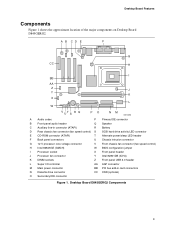
... Components Figure 1 shows the approximate location of the major components on Desktop Board D845GERG2. A B CD E F G CC H I BB AA Z J Y K X L W VUTS R Q PO NM OM13590 A Audio codec P Primary IDE connector B Front panel audio ... intrusion connector G 12 V processor core voltage connector V Front chassis fan connector (fan speed control) H Intel 82845GE (GMCH) W BIOS configuration jumper I Processor socket X Front panel header J Processor fan connector Y Intel 82801DB (ICH4) K DIMM sockets Z Front panel USB 2.0 header L Super I/O controller AA AGP connector ...
... Components Figure 1 shows the approximate location of the major components on Desktop Board D845GERG2. A B CD E F G CC H I BB AA Z J Y K X L W VUTS R Q PO NM OM13590 A Audio codec P Primary IDE connector B Front panel audio ... intrusion connector G 12 V processor core voltage connector V Front chassis fan connector (fan speed control) H Intel 82845GE (GMCH) W BIOS configuration jumper I Processor socket X Front panel header J Processor fan connector Y Intel 82801DB (ICH4) K DIMM sockets Z Front panel USB 2.0 header L Super I/O controller AA AGP connector ...
Product Guide
Page 10
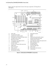
Intel Desktop Board D845GERG2/D845GEBV2 Product Guide Figure 2 shows the approximate location of the major components on Desktop Board D845GEBV2. Desktop Board D845GEBV2 Components 10 A B CD E F G CC H I BB AA Z J Y K L X WV UT S R Q PO NM OM13589 A Audio ...12 V processor core voltage connector V Front chassis fan connector (fan speed control) H Intel 82845GE (GMCH) W BIOS configuration jumper I Processor socket X Front panel header J Processor fan connector (tachometer input) Y Intel 82801DB (ICH4) K DIMM sockets Z Front panel USB header L Super I/O controller ...
Intel Desktop Board D845GERG2/D845GEBV2 Product Guide Figure 2 shows the approximate location of the major components on Desktop Board D845GEBV2. Desktop Board D845GEBV2 Components 10 A B CD E F G CC H I BB AA Z J Y K L X WV UT S R Q PO NM OM13589 A Audio ...12 V processor core voltage connector V Front chassis fan connector (fan speed control) H Intel 82845GE (GMCH) W BIOS configuration jumper I Processor socket X Front panel header J Processor fan connector (tachometer input) Y Intel 82801DB (ICH4) K DIMM sockets Z Front panel USB header L Super I/O controller ...
Product Guide
Page 12
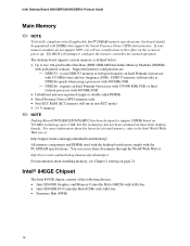
...: - DDR333 memory will run DDR333 memory at power up to the Intel World Wide Web site at: http://support.intel.com/support/motherboards/desktop/ All memory components and DIMMs used with the desktop boards must comply with gold-plated contacts. For more information about installing memory,...BIOS will see Chapter 2 starting on 512 Mbit technology up . If your memory modules do not support SPD, you will attempt to this technology has not been validated on the screen at full speed requires an Intel Pentium 4 processor with 400 MHz FSB. - Intel Desktop Board D845GERG2/D845GEBV2...
...: - DDR333 memory will run DDR333 memory at power up to the Intel World Wide Web site at: http://support.intel.com/support/motherboards/desktop/ All memory components and DIMMs used with the desktop boards must comply with gold-plated contacts. For more information about installing memory,...BIOS will see Chapter 2 starting on 512 Mbit technology up . If your memory modules do not support SPD, you will attempt to this technology has not been validated on the screen at full speed requires an Intel Pentium 4 processor with 400 MHz FSB. - Intel Desktop Board D845GERG2/D845GEBV2...
Product Guide
Page 13
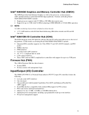
...interface compatible with access to six USB ports Firmware Hub (FWH) The 4 Mbit Firmware Hub has these features: • System BIOS • System security and management logic Input/Output (I/O) Controller The SMSC LPC47M172 or National Semiconductor PC87372 super I /O subsystem with... of the platform. Desktop Board Features Intel® 82845GE Graphics and Memory Controller Hub (GMCH) The GMCH provides Intel Extreme Graphics as well as the processor, system memory, AGP, and hub interfaces in the Intel 845GE chipset platform. Features on Desktop Board D845GERG2/D845GEBV2 include: •...
...interface compatible with access to six USB ports Firmware Hub (FWH) The 4 Mbit Firmware Hub has these features: • System BIOS • System security and management logic Input/Output (I/O) Controller The SMSC LPC47M172 or National Semiconductor PC87372 super I /O subsystem with... of the platform. Desktop Board Features Intel® 82845GE Graphics and Memory Controller Hub (GMCH) The GMCH provides Intel Extreme Graphics as well as the processor, system memory, AGP, and hub interfaces in the Intel 845GE chipset platform. Features on Desktop Board D845GERG2/D845GEBV2 include: •...
Product Guide
Page 15
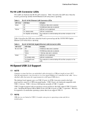
...meets the requirements for a full-speed USB device. Table 3 describes the LED states when the board is communicating with another computer on the LAN. The computer is powered up to operating system ...low-speed USB device is established. Disabling Hi-Speed USB in BIOS reverts all USB 2.0 ports to a USB front panel header. The desktop board supports up and the 10/100 Ethernet LAN subsystem is communicating ...with another computer on the LAN. Desktop Board Features RJ-45 LAN Connector LEDs Two LEDs are backward compatible with...
...meets the requirements for a full-speed USB device. Table 3 describes the LED states when the board is communicating with another computer on the LAN. The computer is powered up to operating system ...low-speed USB device is established. Disabling Hi-Speed USB in BIOS reverts all USB 2.0 ports to a USB front panel header. The desktop board supports up and the 10/100 Ethernet LAN subsystem is communicating ...with another computer on the LAN. Desktop Board Features RJ-45 LAN Connector LEDs Two LEDs are backward compatible with...
Product Guide
Page 17
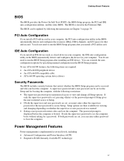
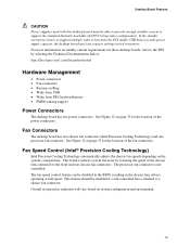
... user restricted access to run the BIOS Setup program after installing an IDE device. Power Management Features Power management is set , you install a PCI add-in card in card. Desktop Board Features BIOS The BIOS provides the Power-On Self-Test (POST), the BIOS Setup program, the PCI and IDE... auto-configuration utilities, and the video BIOS. The BIOS can boot the computer. If both the supervisor and user passwords are...
... user restricted access to run the BIOS Setup program after installing an IDE device. Power Management Features Power management is set , you install a PCI add-in card in card. Desktop Board Features BIOS The BIOS provides the Power-On Self-Test (POST), the BIOS Setup program, the PCI and IDE... auto-configuration utilities, and the video BIOS. The BIOS can boot the computer. If both the supervisor and user passwords are...
Product Guide
Page 19
...The desktop board has two power connectors. For more information on page 33 for the location of the fan connectors. This feature reduces system fan noise by selecting the Technical Documentation link at full speed. The fan speed control feature can be disabled in the BIOS, ... from USB • Wake from the PCI and/or USB buses exceeds power supply capacity, the desktop board may lose register settings stored in the chassis fans always operating at : http://developer.intel.com/design/motherbd/ Hardware Management • Power connectors • Fan connectors • Resume on...
...The desktop board has two power connectors. For more information on page 33 for the location of the fan connectors. This feature reduces system fan noise by selecting the Technical Documentation link at full speed. The fan speed control feature can be disabled in the BIOS, ... from USB • Wake from the PCI and/or USB buses exceeds power supply capacity, the desktop board may lose register settings stored in the chassis fans always operating at : http://developer.intel.com/design/motherbd/ Hardware Management • Power connectors • Fan connectors • Resume on...
Product Guide
Page 21
... only at an ESD workstation using and modifying electronic equipment. 2 Installing and Replacing Desktop Board Components This chapter tells you how to: • Install the I/O shield • Install and remove the desktop board • Install and remove a processor • Install and remove memory •... audio solution • Install the front panel USB solution • Connect fans • Connect power cables • Set the BIOS configuration jumper • Clear passwords • Replace the battery Before You Begin WARNINGS The procedures in this chapter assume familiarity with ...
... only at an ESD workstation using and modifying electronic equipment. 2 Installing and Replacing Desktop Board Components This chapter tells you how to: • Install the I/O shield • Install and remove the desktop board • Install and remove a processor • Install and remove memory •... audio solution • Install the front panel USB solution • Connect fans • Connect power cables • Set the BIOS configuration jumper • Clear passwords • Replace the battery Before You Begin WARNINGS The procedures in this chapter assume familiarity with ...
Product Guide
Page 34
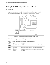
... the jumper. Jumper Setting 31 31 31 Jumper Settings for the BIOS Setup Program Modes (J9H2) Mode Normal (default) (1-2) Configure (2-3) Recovery (None) Description The BIOS uses the current configuration and passwords for the Setup program modes. Intel Desktop Board D845GERG2/D845GEBV2 Product Guide Setting the BIOS Configuration Jumper Block CAUTION Always turn off the power and unplug...
... the jumper. Jumper Setting 31 31 31 Jumper Settings for the BIOS Setup Program Modes (J9H2) Mode Normal (default) (1-2) Configure (2-3) Recovery (None) Description The BIOS uses the current configuration and passwords for the Setup program modes. Intel Desktop Board D845GERG2/D845GEBV2 Product Guide Setting the BIOS Configuration Jumper Block CAUTION Always turn off the power and unplug...
Product Guide
Page 36
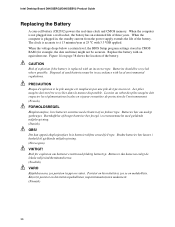
Intel Desktop Board D845GERG2/D845GEBV2 Product Guide Replacing the Battery A coin-cell battery (CR2032) powers the real-time clock and CMOS memory. Risk för explosion om batteriet ersätts ... battery is plugged in, the standby current from the power supply extends the life of the battery. When the voltage drops below a certain level, the BIOS Setup program settings stored in accordance with an incorrect type. PRECAUTION Risque d'explosion si la pile usagée est remplacée par une pile de...
Intel Desktop Board D845GERG2/D845GEBV2 Product Guide Replacing the Battery A coin-cell battery (CR2032) powers the real-time clock and CMOS memory. Risk för explosion om batteriet ersätts ... battery is plugged in, the standby current from the power supply extends the life of the battery. When the voltage drops below a certain level, the BIOS Setup program settings stored in accordance with an incorrect type. PRECAUTION Risque d'explosion si la pile usagée est remplacée par une pile de...
Product Guide
Page 39
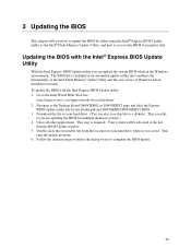
... useful if you are updating the BIOS for the Desktop Board D845GERG2/D845GEBV2 BIOS. 3. Close all other applications. Your system will be rebooted at the last Express BIOS Update window. 5. Follow the instructions provided in the Windows environment. Go to complete the BIOS update. 39 Download the file to... how to recover the BIOS if an update fails. Double-click the executable file from the location on your hard drive. (You can update the system BIOS while in the dialog boxes to the Intel World Wide Web site: http://support.intel.com/support/motherboards/desktop/ 2. This runs the...
... useful if you are updating the BIOS for the Desktop Board D845GERG2/D845GEBV2 BIOS. 3. Close all other applications. Your system will be rebooted at the last Express BIOS Update window. 5. Follow the instructions provided in the Windows environment. Go to complete the BIOS update. 39 Download the file to... how to recover the BIOS if an update fails. Double-click the executable file from the location on your hard drive. (You can update the system BIOS while in the dialog boxes to the Intel World Wide Web site: http://support.intel.com/support/motherboards/desktop/ 2. This runs the...
Product Guide
Page 40
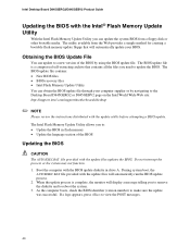
... a new version of the BIOS Updating the BIOS CAUTION The AUTOEXEC.BAT file provided with the BIOS update diskette in drive A. The BIOS update file is complete, the monitor will display a message telling you need to the Desktop Board D845GERG2 or D845GEBV2 page on the Intel World Wide Web site: http://support.intel.com/support/motherboards/desktop ✏ NOTE Please review...
... a new version of the BIOS Updating the BIOS CAUTION The AUTOEXEC.BAT file provided with the BIOS update diskette in drive A. The BIOS update file is complete, the monitor will display a message telling you need to the Desktop Board D845GERG2 or D845GEBV2 page on the Intel World Wide Web site: http://support.intel.com/support/motherboards/desktop ✏ NOTE Please review...
Product Guide
Page 41
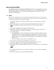
...1 and repeat the recovery process. 8. On the jumper block, reinstall the jumper back on the screen during this procedure. Updating the BIOS Recovering the BIOS It is no video support. See page 34 for Setup. 31 4. Turn off the computer, and disconnect its power cord. 9. Remove... the computer cover and locate the configuration jumper block (see anything will interrupt the BIOS update; Replace the computer cover, connect the power cord, turn off the computer, disconnect the computer's power cord, and disconnect all pins...
...1 and repeat the recovery process. 8. On the jumper block, reinstall the jumper back on the screen during this procedure. Updating the BIOS Recovering the BIOS It is no video support. See page 34 for Setup. 31 4. Turn off the computer, and disconnect its power cord. 9. Remove... the computer cover and locate the configuration jumper block (see anything will interrupt the BIOS update; Replace the computer cover, connect the power cord, turn off the computer, disconnect the computer's power cord, and disconnect all pins...
Product Guide
Page 43
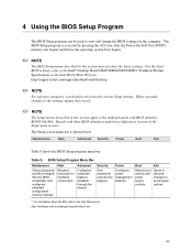
For the latest BIOS settings, refer to the Intel® Desktop Board D845GERG2/D845GEBV2 Technical Product Specification or the Intel World Wide Web site: http://support.intel.com/support/motherboards/desktop ✏ NOTE For reference purposes, you make changes to the settings, update this record. ✏ NOTE The Setup menus described in this section may not ...
For the latest BIOS settings, refer to the Intel® Desktop Board D845GERG2/D845GEBV2 Technical Product Specification or the Intel World Wide Web site: http://support.intel.com/support/motherboards/desktop ✏ NOTE For reference purposes, you make changes to the settings, update this record. ✏ NOTE The Setup menus described in this section may not ...
Product Guide
Page 44
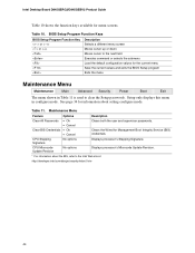
... to clear the Setup passwords. Table 10. See page 34 for the current menu Save the current values and exits the BIOS Setup program Exits the menu Maintenance Menu Maintenance Main Advanced Security Power Boot Exit The menu shown in configure mode. Maintenance Menu... • Cancel CPU Stepping Signature No options Description Clears both the user and supervisor passwords. Displays processor's Stepping Signature. Intel Desktop Board D845GERG2/D845GEBV2 Product Guide Table 10 shows the function keys available for Management Boot Integrity Service (BIS) credentials.
... to clear the Setup passwords. Table 10. See page 34 for the current menu Save the current values and exits the BIOS Setup program Exits the menu Maintenance Menu Maintenance Main Advanced Security Power Boot Exit The menu shown in configure mode. Maintenance Menu... • Cancel CPU Stepping Signature No options Description Clears both the user and supervisor passwords. Displays processor's Stepping Signature. Intel Desktop Board D845GERG2/D845GEBV2 Product Guide Table 10 shows the function keys available for Management Boot Integrity Service (BIS) credentials.


