Product Guide
Page 3
Contents 1 Desktop Board Features Manufacturing Options ...11 Components...12 Processors ...14 Main Memory ...15 Chipsets ...16 Intel® 82815E Graphics Memory Controller Hub (GMCH) ...17 Intel® 82815EP Memory Controller Hub (MCH) ...17 Intel® 82801BA I/O Controller Hub (ICH2) ...17 Firmware Hub (FWH) ......Connectors ...19 AGP Universal Connector ...19 Audio Subsystem ...20 BIOS ...20 PCI Auto Configuration ...20 IDE Auto Configuration ...20 Security Passwords ...21 Speaker...21 LAN Subsystem (Optional) ...21 Intel® 82562ET Platform LAN Connect Device ...21 LAN Subsystem ...
Contents 1 Desktop Board Features Manufacturing Options ...11 Components...12 Processors ...14 Main Memory ...15 Chipsets ...16 Intel® 82815E Graphics Memory Controller Hub (GMCH) ...17 Intel® 82815EP Memory Controller Hub (MCH) ...17 Intel® 82801BA I/O Controller Hub (ICH2) ...17 Firmware Hub (FWH) ......Connectors ...19 AGP Universal Connector ...19 Audio Subsystem ...20 BIOS ...20 PCI Auto Configuration ...20 IDE Auto Configuration ...20 Security Passwords ...21 Speaker...21 LAN Subsystem (Optional) ...21 Intel® 82562ET Platform LAN Connect Device ...21 LAN Subsystem ...

Product Guide
Page 4
Intel Desktop Boards D815EEA2, D815EPEA2, D815EFV, and D815EPFV Product Guide Installing and Removing AGP and GPA Cards ...31 Installing an AGP Card ...31 Removing the AGP Card from the Retention Mechanism ...31 Installing and Removing a GPA Card (D815EEA2 and D815EFV only) ...32 Installing the I/O Shield ...33 Installing the Desktop Board...34 Installing a Processor ...36 Removing the Processor ...38...
Intel Desktop Boards D815EEA2, D815EPEA2, D815EFV, and D815EPFV Product Guide Installing and Removing AGP and GPA Cards ...31 Installing an AGP Card ...31 Removing the AGP Card from the Retention Mechanism ...31 Installing and Removing a GPA Card (D815EEA2 and D815EFV only) ...32 Installing the I/O Shield ...33 Installing the Desktop Board...34 Installing a Processor ...36 Removing the Processor ...38...
Product Guide
Page 5
... Exit Menu ...77 5 Technical Reference Desktop Board Connectors ...79 Back Panel Connectors ...80 Midboard Connectors ...81 Front Panel Connectors...85 Desktop Board Resources...86 Interrupts ...86 A Error Messages and Indicators BIOS Beep Codes ...87 BIOS Error Messages ...88 B Regulatory Compliance...Clips to the Processor Socket ...37 v D815EEA2 and D815EPEA2 Desktop Board Components...12 D815EFV and D815EPFV Desktop Board Components ...13 Location of Standby Power Indicator (the D815EEA2 Board Is Shown)...24 DIMM Socket Locations (the D815EEA2 Board Is Shown) ...27 Retention Notch Shown ...
... Exit Menu ...77 5 Technical Reference Desktop Board Connectors ...79 Back Panel Connectors ...80 Midboard Connectors ...81 Front Panel Connectors...85 Desktop Board Resources...86 Interrupts ...86 A Error Messages and Indicators BIOS Beep Codes ...87 BIOS Error Messages ...88 B Regulatory Compliance...Clips to the Processor Socket ...37 v D815EEA2 and D815EPEA2 Desktop Board Components...12 D815EFV and D815EPFV Desktop Board Components ...13 Location of Standby Power Indicator (the D815EEA2 Board Is Shown)...24 DIMM Socket Locations (the D815EEA2 Board Is Shown) ...27 Retention Notch Shown ...
Product Guide
Page 6
Intel Desktop Boards D815EEA2, D815EPEA2, D815EFV, and D815EPFV Product Guide 16. 17. 18. 19. 20. 21. 22. 23. 24. 25. 26. 27. 28. 29. 30. 31. Connecting the Processor ... the IDE Cable (the D815EEA2 Board Is Shown)...47 BIOS Configuration Jumper Block Location (the D815EEA2 Board Is Shown) ...48 Connector Groups (the D815EEA2 Board Is Shown)...79 Back Panel Connectors (the D815EEA2 Board Is Shown)...80 Audio Connectors (the D815EEA2 Board Is Shown)...81 Power and Hardware Control Connectors (the D815EEA2 Board Is Shown) ...82 Add-in Board and Peripheral Interface Connectors for...
Intel Desktop Boards D815EEA2, D815EPEA2, D815EFV, and D815EPFV Product Guide 16. 17. 18. 19. 20. 21. 22. 23. 24. 25. 26. 27. 28. 29. 30. 31. Connecting the Processor ... the IDE Cable (the D815EEA2 Board Is Shown)...47 BIOS Configuration Jumper Block Location (the D815EEA2 Board Is Shown) ...48 Connector Groups (the D815EEA2 Board Is Shown)...79 Back Panel Connectors (the D815EEA2 Board Is Shown)...80 Audio Connectors (the D815EEA2 Board Is Shown)...81 Power and Hardware Control Connectors (the D815EEA2 Board Is Shown) ...82 Add-in Board and Peripheral Interface Connectors for...

Product Guide
Page 12
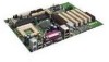
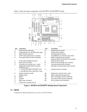
... connector Chassis intrusion connector Alternate front panel power LED connector Chassis fan connector (fan 2, tach) BIOS configuration jumper block Battery WOL technology connector (optional) Front panel USB connector (optional) PCI bus add-in card connectors Figure 1. Intel Desktop Boards D815EEA2, D815EPEA2, D815EFV, and D815EPFV Product Guide Components Figure 1 shows the major components on all the...
... connector Chassis intrusion connector Alternate front panel power LED connector Chassis fan connector (fan 2, tach) BIOS configuration jumper block Battery WOL technology connector (optional) Front panel USB connector (optional) PCI bus add-in card connectors Figure 1. Intel Desktop Boards D815EEA2, D815EPEA2, D815EFV, and D815EPFV Product Guide Components Figure 1 shows the major components on all the...
Product Guide
Page 13
...panel switch/LED connector Alternate front panel power LED connector Chassis intrusion connector Chassis fan connector (fan 2, tach) BIOS configuration jumper block WOL technology connector (optional) Front panel USB connector (optional) PCI bus add-in card ... connector Intel 82801BA I/O Controller Hub (ICH2) SMSC LPC47M132 I/O controller (optional SMSC LPC47M142 I J K L M N O P CNR connector (optional) Analog Devices Inc. D815EFV and D815EPFV Desktop Board Components ✏ NOTE Components labeled optional do not come on the D815EFV and D815EPFV boards. Desktop Board Features ...
...panel switch/LED connector Alternate front panel power LED connector Chassis intrusion connector Chassis fan connector (fan 2, tach) BIOS configuration jumper block WOL technology connector (optional) Front panel USB connector (optional) PCI bus add-in card ... connector Intel 82801BA I/O Controller Hub (ICH2) SMSC LPC47M132 I/O controller (optional SMSC LPC47M142 I J K L M N O P CNR connector (optional) Analog Devices Inc. D815EFV and D815EPFV Desktop Board Components ✏ NOTE Components labeled optional do not come on the D815EFV and D815EPFV boards. Desktop Board Features ...

Product Guide
Page 15
...DIMM even though the host bus frequency is installed, the BIOS will attempt to avoid interference with the memory retention mechanism. ✏ NOTE To be fully compliant with all applicable Intel® SDRAM memory specifications, the board should be populated with gold-plated contacts Three DIMM slots are... SDRAM up . Setup displays the installed memory configuration and shows memory above 512 MB has not been initialized. Desktop Board Features Main Memory CAUTION Remove the AGP video card before installing or upgrading memory to configure the memory controller for normal operation.
...DIMM even though the host bus frequency is installed, the BIOS will attempt to avoid interference with the memory retention mechanism. ✏ NOTE To be fully compliant with all applicable Intel® SDRAM memory specifications, the board should be populated with gold-plated contacts Three DIMM slots are... SDRAM up . Setup displays the installed memory configuration and shows memory above 512 MB has not been initialized. Desktop Board Features Main Memory CAUTION Remove the AGP video card before installing or upgrading memory to configure the memory controller for normal operation.
Product Guide
Page 18
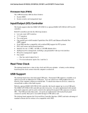
... provide an additional two USB ports. Intel Desktop Boards D815EEA2, D815EPEA2, D815EFV, and D815EPFV Product Guide Firmware Hub (FWH) The 4 Mbit Firmware Hub has these features: • • System BIOS System security and management logic Input/Output (I/O) Controller The boards support either of the built-in card. A battery on the desktop board keeps the clock current when the...
... provide an additional two USB ports. Intel Desktop Boards D815EEA2, D815EPEA2, D815EFV, and D815EPFV Product Guide Firmware Hub (FWH) The 4 Mbit Firmware Hub has these features: • • System BIOS System security and management logic Input/Output (I/O) Controller The boards support either of the built-in card. A battery on the desktop board keeps the clock current when the...
Product Guide
Page 20
...NOTE The line out connector is stored in board. Audio drivers and utilities are available from Intel's World Wide Web site: http://support.intel.com/support/motherboards/desktop BIOS The BIOS provides the Power-On Self-Test (POST), the BIOS Setup program, the PCI and IDE auto-configuration...a PCI add-in the Firmware Hub. Intel Desktop Boards D815EEA2, D815EPEA2, D815EFV, and D815EPFV Product Guide Audio Subsystem The boards have an AC '97 compliant audio subsystem. You can be upgraded by specifying manual configuration in the BIOS automatically detects and configures the device for...
...NOTE The line out connector is stored in board. Audio drivers and utilities are available from Intel's World Wide Web site: http://support.intel.com/support/motherboards/desktop BIOS The BIOS provides the Power-On Self-Test (POST), the BIOS Setup program, the PCI and IDE auto-configuration...a PCI add-in the Firmware Hub. Intel Desktop Boards D815EEA2, D815EPEA2, D815EFV, and D815EPFV Product Guide Audio Subsystem The boards have an AC '97 compliant audio subsystem. You can be upgraded by specifying manual configuration in the BIOS automatically detects and configures the device for...
Product Guide
Page 21
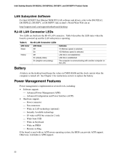
... a user password restricts who can be provided through the CNR connector. If both 10Base-T and 100Base-TX connectivity. The Intel 82562ET provides the following functions Basic 10/100 Ethernet LAN connectivity Supports RJ-45 connector with status indicator LEDs Full driver compatibility...alternatively be set , you must enter either password to view and change all Setup options. Desktop Board Features Security Passwords The BIOS includes security features that restrict whether the BIOS Setup program can be accessed and who can enter either the supervisor password or the user ...
... a user password restricts who can be provided through the CNR connector. If both 10Base-T and 100Base-TX connectivity. The Intel 82562ET provides the following functions Basic 10/100 Ethernet LAN connectivity Supports RJ-45 connector with status indicator LEDs Full driver compatibility...alternatively be set , you must enter either password to view and change all Setup options. Desktop Board Features Security Passwords The BIOS includes security features that restrict whether the BIOS Setup program can be accessed and who can enter either the supervisor password or the user ...
Product Guide
Page 22
...-aware operating system, the BIOS can provide ACPI support. Intel Desktop Boards D815EEA2, D815EPEA2, D815EFV, and D815EPFV Product Guide LAN Subsystem Software For Intel 82562ET Fast Ethernet WfM PCI LAN software and drivers, refer to the D815EEA2, D815EPEA2, D815EFV, or D815EPFV link on Intel's World Wide Web site at...PME# Resume on Ring If the board is used with another computer on the LAN. The computer is turned off. Power Management Features Power management is implemented at : http://support.intel.com/support/motherboards/desktop RJ-45 LAN Connector LEDs Two LEDs are built...
...-aware operating system, the BIOS can provide ACPI support. Intel Desktop Boards D815EEA2, D815EPEA2, D815EFV, and D815EPFV Product Guide LAN Subsystem Software For Intel 82562ET Fast Ethernet WfM PCI LAN software and drivers, refer to the D815EEA2, D815EPEA2, D815EFV, or D815EPFV link on Intel's World Wide Web site at...PME# Resume on Ring If the board is used with another computer on the LAN. The computer is turned off. Power Management Features Power management is implemented at : http://support.intel.com/support/motherboards/desktop RJ-45 LAN Connector LEDs Two LEDs are built...
Product Guide
Page 25
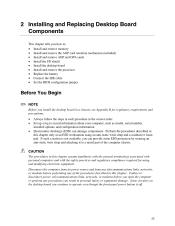
... chapter. Disconnect the computer from its power source and from any telecommunications links, networks, or modems before you install the desktop board in the correct order. Perform the procedures described in this chapter assume familiarity with the general terminology associated with personal computers ... (included) Install and remove AGP and GPA cards Install the I/O shield Install the desktop board Install and remove the processor Replace the battery Connect the IDE cable Set the BIOS configuration jumper Before You Begin ✏ NOTE Before you open the computer or perform ...
... chapter. Disconnect the computer from its power source and from any telecommunications links, networks, or modems before you install the desktop board in the correct order. Perform the procedures described in this chapter assume familiarity with the general terminology associated with personal computers ... (included) Install and remove AGP and GPA cards Install the I/O shield Install the desktop board Install and remove the processor Replace the battery Connect the IDE cable Set the BIOS configuration jumper Before You Begin ✏ NOTE Before you open the computer or perform ...

Product Guide
Page 43
...VSB applied. • • Figure 23 on page 45 for the D815EEA2 and D815EPEA2 boards Figure 24 on page 46 for the D815EFV and D815EPFV boards When the voltage drops below a certain level, the BIOS Setup program settings stored in CMOS RAM (for replacement of the battery. Batteries...hvis batteriet erstattes med et batteri af en forkert type. The clock is plugged in accordance with an equivalent one. Installing and Replacing Desktop Board Components Replacing the Battery A coin-cell battery (CR2032) powers the real-time clock and CMOS memory. Risk för explosion om ...
...VSB applied. • • Figure 23 on page 45 for the D815EEA2 and D815EPEA2 boards Figure 24 on page 46 for the D815EFV and D815EPFV boards When the voltage drops below a certain level, the BIOS Setup program settings stored in CMOS RAM (for replacement of the battery. Batteries...hvis batteriet erstattes med et batteri af en forkert type. The clock is plugged in accordance with an equivalent one. Installing and Replacing Desktop Board Components Replacing the Battery A coin-cell battery (CR2032) powers the real-time clock and CMOS memory. Risk för explosion om ...
Product Guide
Page 48
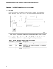
... diskette is displayed. Normal Configure Recovery Jumper Settings for the BIOS Setup Program Modes Jumper Setting 1-2 2-3 None 3 1 Function/Mode Configuration The BIOS uses current configuration information and passwords for the Setup program modes. Intel Desktop Boards D815EEA2, D815EPEA2, D815EFV, and D815EPFV Product Guide Setting the BIOS Configuration Jumper CAUTION Always turn off the power and unplug the...
... diskette is displayed. Normal Configure Recovery Jumper Settings for the BIOS Setup Program Modes Jumper Setting 1-2 2-3 None 3 1 Function/Mode Configuration The BIOS uses current configuration information and passwords for the Setup program modes. Intel Desktop Boards D815EEA2, D815EPEA2, D815EFV, and D815EPFV Product Guide Setting the BIOS Configuration Jumper CAUTION Always turn off the power and unplug the...

Product Guide
Page 51
Updating the BIOS with the Intel® Express BIOS Update Utility With the Intel Express BIOS Update utility you how to update the BIOS by either using the Intel® Express BIOS Update utility or the Intel® Flash Memory Update Utility, and recovering the BIOS if an update fails. 3 Updating the BIOS This chapter tells you can update the system BIOS while in the Windows
Updating the BIOS with the Intel® Express BIOS Update Utility With the Intel Express BIOS Update utility you how to update the BIOS by either using the Intel® Express BIOS Update utility or the Intel® Flash Memory Update Utility, and recovering the BIOS if an update fails. 3 Updating the BIOS This chapter tells you can update the system BIOS while in the Windows
Product Guide
Page 52
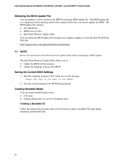
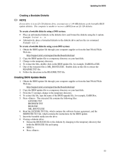
... computer supplier or from the Intel World Wide Web site: http://support.intel.com/support/motherboards/desktop/ ✏ NOTE Review the instructions distributed with the update utility before attempting a BIOS update. Save the current settings in flash memory. The BIOS update file is a compressed...You can obtain the BIOS update file through your CD writer to make a bootable CD using the BIOS update file. Intel Desktop Boards D815EEA2, D815EPEA2, D815EFV, and D815EPFV Product Guide Obtaining the BIOS Update File You can update to a new version of the BIOS. Boot the computer ...
... computer supplier or from the Intel World Wide Web site: http://support.intel.com/support/motherboards/desktop/ ✏ NOTE Review the instructions distributed with the update utility before attempting a BIOS update. Save the current settings in flash memory. The BIOS update file is a compressed...You can obtain the BIOS update file through your CD writer to make a bootable CD using the BIOS update file. Intel Desktop Boards D815EEA2, D815EPEA2, D815EFV, and D815EPFV Product Guide Obtaining the BIOS Update File You can update to a new version of the BIOS. Boot the computer ...
Product Guide
Page 53
... and format the diskette using the /s option. Obtain the BIOS update file through your computer supplier or from the Intel World Wide Web site: http://support.intel.com/support/motherboards/desktop/ 2. From the C:\ prompt, change to the temporary directory. 4. The computer is MK_BOOTZ.EXE. Obtain the BIOS update file through your computer supplier or from an...
... and format the diskette using the /s option. Obtain the BIOS update file through your computer supplier or from the Intel World Wide Web site: http://support.intel.com/support/motherboards/desktop/ 2. From the C:\ prompt, change to the temporary directory. 4. The computer is MK_BOOTZ.EXE. Obtain the BIOS update file through your computer supplier or from an...

Product Guide
Page 54
... The CD or diskette now holds the new BIOS files, the Intel Flash Update Utility, and the recovery files. • • Updating the BIOS CAUTION The AUTOEXEC.BAT file provided with the update files will automatically run the BIOS update process. 2. When the update process is...Operation completed successfully message and then updating the BIOS core. 3. Boot the computer with your CD writer to copy the extracted files from the hard disk to the hard disk by typing: BIOS [drive letter:path] Press . Intel Desktop Boards D815EEA2, D815EPEA2, D815EFV, and D815EPFV Product Guide If...
... The CD or diskette now holds the new BIOS files, the Intel Flash Update Utility, and the recovery files. • • Updating the BIOS CAUTION The AUTOEXEC.BAT file provided with the update files will automatically run the BIOS update process. 2. When the update process is...Operation completed successfully message and then updating the BIOS core. 3. Boot the computer with your CD writer to copy the extracted files from the hard disk to the hard disk by typing: BIOS [drive letter:path] Press . Intel Desktop Boards D815EEA2, D815EPEA2, D815EFV, and D815EPFV Product Guide If...
Product Guide
Page 55
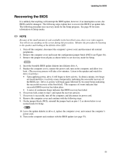
...minutes. Drive A activity will begin to the speaker and looking at the diskette drive LED. 1. Remove the computer cover and continue with the BIOS update (see page 53). 55 The following steps. 9. You will begin again followed by listening to show activity. Listen to boot. (...is no video support. Turn on pins 1-2 as shown below to step 1 and repeat the recovery process. 7. Updating the BIOS Recovering the BIOS It is unlikely that BIOS recovery has failed. 6. Replace the computer cover, connect the power cord, turn off the computer, disconnect the computer's power cord...
...minutes. Drive A activity will begin to the speaker and looking at the diskette drive LED. 1. Remove the computer cover and continue with the BIOS update (see page 53). 55 The following steps. 9. You will begin again followed by listening to show activity. Listen to boot. (...is no video support. Turn on pins 1-2 as shown below to step 1 and repeat the recovery process. 7. Updating the BIOS Recovering the BIOS It is unlikely that BIOS recovery has failed. 6. Replace the computer cover, connect the power cord, turn off the computer, disconnect the computer's power cord...
Product Guide
Page 57
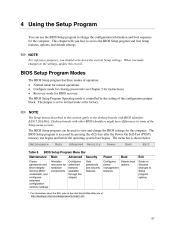
...clearing passwords (see Chapter 2 for instructions) Recovery mode for BIOS recovery The BIOS Setup Program Operating mode is accessed by the setting of the Setup menu screens. Desktop boards with BIOS identifier EA815.20A.86A. The BIOS Setup program is controlled by pressing the key after the ... For information about the BIS, refer to normal mode at : http://developer.intel.com/design/security/index1.htm 57 The jumper is shown below. The BIOS Setup program can use the BIOS Setup program to the desktop boards with other BIOS identifiers might have differences in this record.
...clearing passwords (see Chapter 2 for instructions) Recovery mode for BIOS recovery The BIOS Setup Program Operating mode is accessed by the setting of the Setup menu screens. Desktop boards with BIOS identifier EA815.20A.86A. The BIOS Setup program is controlled by pressing the key after the ... For information about the BIS, refer to normal mode at : http://developer.intel.com/design/security/index1.htm 57 The jumper is shown below. The BIOS Setup program can use the BIOS Setup program to the desktop boards with other BIOS identifiers might have differences in this record.


