
Product Guide
Page 7
... PCI Express x16 Card 34 16. Location of the Standby Power Indicator 20 4. Desktop Boards D102GGC2 Components 12 3. Beep Codes...55 11. Safety Regulations...57 13. Intel Desktop Board D102GGC2 Components 11 2. Remove the Processor from the Protective Processor Cover/Do Not Touch 28 10. ...Connecting the Serial ATA Cable 37 19. Connecting 2 x 12 Power Supply Cables 43 23. Power Supply Requirements 13 4. Lift the Load Plate and Don't Touch the Socket Contacts 27 8. Jumper Settings for High Definition Audio 39 6. Back Panel Audio Connectors for a Flexible 6-Channel...
... PCI Express x16 Card 34 16. Location of the Standby Power Indicator 20 4. Desktop Boards D102GGC2 Components 12 3. Beep Codes...55 11. Safety Regulations...57 13. Intel Desktop Board D102GGC2 Components 11 2. Remove the Processor from the Protective Processor Cover/Do Not Touch 28 10. ...Connecting the Serial ATA Cable 37 19. Connecting 2 x 12 Power Supply Cables 43 23. Power Supply Requirements 13 4. Lift the Load Plate and Don't Touch the Socket Contacts 27 8. Jumper Settings for High Definition Audio 39 6. Back Panel Audio Connectors for a Flexible 6-Channel...
Product Guide
Page 13
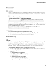
...power connectors, page 43 in Chapter 2 Main Memory NOTE To be fully compliant with all applicable Intel® SDRAM memory specifications, the board should be purchased separately. Processors are not included with gold-plated contacts • Support for: ⎯ Unbuffered, non-registered DIMMs ⎯ Serial Presence Detect .... The processor connects to configure the memory controller for 10 ms ATX12V (version 2.0 or greater) compliant power supply Desktop board D102GGC2 supports an Intel processor in damage to the board, or the system may result in the LGA775 package.
...power connectors, page 43 in Chapter 2 Main Memory NOTE To be fully compliant with all applicable Intel® SDRAM memory specifications, the board should be purchased separately. Processors are not included with gold-plated contacts • Support for: ⎯ Unbuffered, non-registered DIMMs ⎯ Serial Presence Detect .... The processor connects to configure the memory controller for 10 ms ATX12V (version 2.0 or greater) compliant power supply Desktop board D102GGC2 supports an Intel processor in damage to the board, or the system may result in the LGA775 package.
Product Guide
Page 27
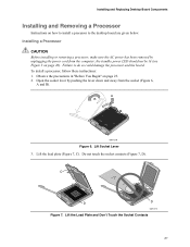
... board are given below. A B OM17210 Figure 6. Open the socket lever by unplugging the power cord from the socket (Figure 6, A and B). Lift the load plate (Figure 7, C). Lift the Load Plate and Don't Touch the Socket Contacts 27 Do not touch the socket contacts (Figure 7, D). Lift Socket Lever 3. Observe the precautions in "Before You...
... board are given below. A B OM17210 Figure 6. Open the socket lever by unplugging the power cord from the socket (Figure 6, A and B). Lift the load plate (Figure 7, C). Lift the Load Plate and Don't Touch the Socket Contacts 27 Do not touch the socket contacts (Figure 7, D). Lift Socket Lever 3. Observe the precautions in "Before You...

Product Guide
Page 28
Remove the processor from the load plate (Figure 8, E). Remove the plastic protective socket cover from the protective processor cover. E OM17228 Figure 8. Do not discard the protective processor cover. Always replace the processor ... Protective Socket Cover 5. Remove the Processor from the socket. OM17213 Figure 9. Always replace the socket cover if the processor is removed from the socket. Intel Desktop Board D102GGC2 Product Guide 4. Do not discard the protective socket cover. Hold the processor only at the edges, being careful not to the package if the...
Remove the processor from the load plate (Figure 8, E). Remove the plastic protective socket cover from the protective processor cover. E OM17228 Figure 8. Do not discard the protective processor cover. Always replace the processor ... Protective Socket Cover 5. Remove the Processor from the socket. OM17213 Figure 9. Always replace the socket cover if the processor is removed from the socket. Intel Desktop Board D102GGC2 Product Guide 4. Do not discard the protective socket cover. Hold the processor only at the edges, being careful not to the package if the...

Product Guide
Page 29
J I ), close and engage the socket lever (Figure 11, J). Hold the processor with the socket (Figure 10, H). Install Processor OM17214 7. Close the Load Plate 29 Installing and Replacing Desktop Board Components 6. Make sure fingers align to the socket cutouts (Figure 10, F). G G H F H F Figure 10. Align notches (Figure 10, G) with your thumb and index fingers oriented as shown in the socket. While pressing down without tilting or sliding the processor in Figure 10. Lower the processor straight down on the load plate (Figure 11, I OM17215 Figure 11.
J I ), close and engage the socket lever (Figure 11, J). Hold the processor with the socket (Figure 10, H). Install Processor OM17214 7. Close the Load Plate 29 Installing and Replacing Desktop Board Components 6. Make sure fingers align to the socket cutouts (Figure 10, F). G G H F H F Figure 10. Align notches (Figure 10, G) with your thumb and index fingers oriented as shown in the socket. While pressing down without tilting or sliding the processor in Figure 10. Lower the processor straight down on the load plate (Figure 11, I OM17215 Figure 11.