

Product Specification
Page 5
... Options 11 1.1.3 Board Layout 12 1.1.4 Block Diagram 14 1.2 Online Support ...15 1.3 Processor ...15 1.4 System Memory ...16 1.4.1 Memory Configurations 17 1.5 Intel® 955X Chipset...21 1.5.1 USB ...21 1.5.2 IDE Support 21 1.5.3 Real-Time Clock, CMOS SRAM, and Battery 23 1.6 Discrete Serial ATA Interface (Optional 24 1.7 PCI Express* Connectors 24 1.8 Auxiliary Power (AUX PWR) Connector (Optional 25 1.9 IEEE-1394a/b Connectors (Optional 25 1.10 Legacy I/O Controller 26 1.10.1 Serial Port...26 1.10.2 Parallel Port 26 1.10.3 Diskette Drive Controller 26 1.10.4 Keyboard...
... Options 11 1.1.3 Board Layout 12 1.1.4 Block Diagram 14 1.2 Online Support ...15 1.3 Processor ...15 1.4 System Memory ...16 1.4.1 Memory Configurations 17 1.5 Intel® 955X Chipset...21 1.5.1 USB ...21 1.5.2 IDE Support 21 1.5.3 Real-Time Clock, CMOS SRAM, and Battery 23 1.6 Discrete Serial ATA Interface (Optional 24 1.7 PCI Express* Connectors 24 1.8 Auxiliary Power (AUX PWR) Connector (Optional 25 1.9 IEEE-1394a/b Connectors (Optional 25 1.10 Legacy I/O Controller 26 1.10.1 Serial Port...26 1.10.2 Parallel Port 26 1.10.3 Diskette Drive Controller 26 1.10.4 Keyboard...

Product Specification
Page 7
Dual Channel (Interleaved) Mode Configuration with Intel® Rapid BIOS Boot 84 3.7.1 Peripheral Selection and Configuration 84 3.7.2 Intel Rapid BIOS Boot 84 3.8 BIOS Security Features 85 4 Error Messages and Beep Codes 4.1 Speaker ...87 4.2 BIOS Beep Codes...87 4.3 BIOS Error Messages 87 4.4 Port 80h POST Codes 88 Figures 1. Front/Back Panel Audio Connector Options for 8-Channel (7.1) Audio Subsystem .... 28 10. 8-channel (7.1) Audio Subsystem Block Diagram 29 11. Location of the Jumper Block 65 24. Localized High Temperature Zones 72 Tables 1. Manufacturing Options...
Dual Channel (Interleaved) Mode Configuration with Intel® Rapid BIOS Boot 84 3.7.1 Peripheral Selection and Configuration 84 3.7.2 Intel Rapid BIOS Boot 84 3.8 BIOS Security Features 85 4 Error Messages and Beep Codes 4.1 Speaker ...87 4.2 BIOS Beep Codes...87 4.3 BIOS Error Messages 87 4.4 Port 80h POST Codes 88 Figures 1. Front/Back Panel Audio Connector Options for 8-Channel (7.1) Audio Subsystem .... 28 10. 8-channel (7.1) Audio Subsystem Block Diagram 29 11. Location of the Jumper Block 65 24. Localized High Temperature Zones 72 Tables 1. Manufacturing Options...

Product Specification
Page 8
... User Password Functions 85 45. Port 80h POST Code Ranges 88 48. System Memory Map 45 10. PCI Configuration Space Map 47 13. Front Panel Audio Connector 56 20. Front Chassis Fan and Rear Chassis Fan Connectors 56 21. Serial ATA Connectors 57 24. Auxiliary Front Panel Power/Sleep LED Connector 60 30. States for a One-Color Power LED 62 32. EMC Regulations ...75 40. BIOS Setup Program Menu Bar 80 42. Beep Codes ...87 46. BIOS Setup Configuration Jumper Settings 65 34. Boot Device Menu Options 83 44. Wake...
... User Password Functions 85 45. Port 80h POST Code Ranges 88 48. System Memory Map 45 10. PCI Configuration Space Map 47 13. Front Panel Audio Connector 56 20. Front Chassis Fan and Rear Chassis Fan Connectors 56 21. Serial ATA Connectors 57 24. Auxiliary Front Panel Power/Sleep LED Connector 60 30. States for a One-Color Power LED 62 32. EMC Regulations ...75 40. BIOS Setup Program Menu Bar 80 42. Beep Codes ...87 46. BIOS Setup Configuration Jumper Settings 65 34. Boot Device Menu Options 83 44. Wake...

Product Specification
Page 10
... Flash device) • Support for Advanced Configuration and Power Interface (ACPI), Plug and Play, SMBIOS, and Intel® Active Management Technology (Intel® AMT) • Support for PCI Local Bus Specification Revision 2.3 • Support for PCI Express* Revision 1.0a • Suspend to RAM support • Wake on PCI, RS-232, front panel, PS/2 devices, and USB ports Gigabit (10/100/1000 Mbits/sec) LAN subsystem using the Intel® 82573E/82573V Gigabit Ethernet Controller • Four PCI Conventional* bus add-in card connectors...
... Flash device) • Support for Advanced Configuration and Power Interface (ACPI), Plug and Play, SMBIOS, and Intel® Active Management Technology (Intel® AMT) • Support for PCI Local Bus Specification Revision 2.3 • Support for PCI Express* Revision 1.0a • Suspend to RAM support • Wake on PCI, RS-232, front panel, PS/2 devices, and USB ports Gigabit (10/100/1000 Mbits/sec) LAN subsystem using the Intel® 82573E/82573V Gigabit Ethernet Controller • Four PCI Conventional* bus add-in card connectors...

Product Specification
Page 14
...) PCI Slot 1 PCI Slot 2 PCI Slot 3 PCI Slot 4 Discrete SATA RAID Controller (Optional) PCI Bus PCI Bus SMBus Hardware Monitoring and Fan Control ASIC High Definition Audio Link SATA IDE Interface TPM Component (Optional) SATA IDE Connectors (4) Front Panel Mic In Front Panel Line Out Audio Codec Mic In/Retasking Jack Line In/Retasking Jack Line Out/Retasking Jack CD-ROM (Optional) S/PDIF Center and LFE/Retasking Jack Surround Left-Right/Retasking Jack Figure 2. Block Diagram OM17986 14 or -- Intel Desktop Board D955XCS Technical Product Specification 1.1.4 Block Diagram...
...) PCI Slot 1 PCI Slot 2 PCI Slot 3 PCI Slot 4 Discrete SATA RAID Controller (Optional) PCI Bus PCI Bus SMBus Hardware Monitoring and Fan Control ASIC High Definition Audio Link SATA IDE Interface TPM Component (Optional) SATA IDE Connectors (4) Front Panel Mic In Front Panel Line Out Audio Codec Mic In/Retasking Jack Line In/Retasking Jack Line Out/Retasking Jack CD-ROM (Optional) S/PDIF Center and LFE/Retasking Jack Surround Left-Right/Retasking Jack Figure 2. Block Diagram OM17986 14 or -- Intel Desktop Board D955XCS Technical Product Specification 1.1.4 Block Diagram...

Product Specification
Page 21
... the USB controller for full-speed devices. For information about The Intel 955X chipset Resources used by the chipset Refer to http://developer.intel.com/ Chapter 2 1.5.1 USB The board supports up to 66 MB/sec. The Parallel ATA IDE interface supports the following devices: • Intel 82955X Memory Controller Hub (MCH) with Direct Media Interface (DMI) interconnect • Intel 82801GR I/O Controller Hub (ICH7-R) with dual stacked back panel connectors adjacent to the audio connectors • Four ports...
... the USB controller for full-speed devices. For information about The Intel 955X chipset Resources used by the chipset Refer to http://developer.intel.com/ Chapter 2 1.5.1 USB The board supports up to 66 MB/sec. The Parallel ATA IDE interface supports the following devices: • Intel 82955X Memory Controller Hub (MCH) with Direct Media Interface (DMI) interconnect • Intel 82801GR I/O Controller Hub (ICH7-R) with dual stacked back panel connectors adjacent to the audio connectors • Four ports...

Product Specification
Page 25
...; Support for internal chassis lighting or additional fans. IEEE-1394b operation is completely compatible with these precautions may cause damage to 400 Mbits/sec. The IEEE-1394a interface provides a throughput ranging from 100 Mbits/sec to the board. The IEEE-1394b interface is not supported. • Two IEEE-1394a/b front-panel connectors located on the back panel. The default setting in the BIOS is controlled from...
...; Support for internal chassis lighting or additional fans. IEEE-1394b operation is completely compatible with these precautions may cause damage to 400 Mbits/sec. The IEEE-1394a interface provides a throughput ranging from 100 Mbits/sec to the board. The IEEE-1394b interface is not supported. • Two IEEE-1394a/b front-panel connectors located on the back panel. The default setting in the BIOS is controlled from...
Product Specification
Page 32
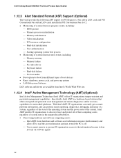
... in PCI Conventional bus slot 2: • Monitoring of system firmware progress events, including: ⎯ BIOS present ⎯ Primary processor initialization ⎯ Memory initialization ⎯ Video initialization ⎯ PCI resource configuration ⎯ Hard-disk initialization ⎯ User authentication ⎯ Starting operating system boot process • Monitoring of system firmware error events, including: ⎯ Memory missing ⎯ Memory failure ⎯ No video device ⎯ Keyboard failure ⎯ Hard-disk failure ⎯ No boot media • Boot options to boot...
... in PCI Conventional bus slot 2: • Monitoring of system firmware progress events, including: ⎯ BIOS present ⎯ Primary processor initialization ⎯ Memory initialization ⎯ Video initialization ⎯ PCI resource configuration ⎯ Hard-disk initialization ⎯ User authentication ⎯ Starting operating system boot process • Monitoring of system firmware error events, including: ⎯ Memory missing ⎯ Memory failure ⎯ No video device ⎯ Keyboard failure ⎯ Hard-disk failure ⎯ No boot media • Boot options to boot...

Product Specification
Page 39
...; WAKE# signal wake-up event from specific states. The method used . LAN Modem (back panel Serial Port A) PME# signal Power switch PS/2 devices RTC alarm USB WAKE# ...from the +5 V standby line. Failure to access the computer when it is disabled by default in a power-managed state. Wake-up Devices and Events These devices/events can damage the power supply. Table 8. NOTE The use of telephony device (external or internal). 39 In addition, software, drivers, and peripherals must fully support ACPI wake...
...; WAKE# signal wake-up event from specific states. The method used . LAN Modem (back panel Serial Port A) PME# signal Power switch PS/2 devices RTC alarm USB WAKE# ...from the +5 V standby line. Failure to access the computer when it is disabled by default in a power-managed state. Wake-up Devices and Events These devices/events can damage the power supply. Table 8. NOTE The use of telephony device (external or internal). 39 In addition, software, drivers, and peripherals must fully support ACPI wake...

Product Specification
Page 43
... MB) • Front side bus interrupts (17 MB) • PCI Express configuration space (256 MB) • MCH base address registers, internal graphics ranges, PCI Express ports (up to reclaim the physical memory overlapped by the memory mapped I/O logical address space. All installed system memory can be used when there is dynamically allocated for PCI Conventional and PCI Express add-in cards, PCI Express configuration space, BIOS (firmware hub), and chipset overhead resides above the...
... MB) • Front side bus interrupts (17 MB) • PCI Express configuration space (256 MB) • MCH base address registers, internal graphics ranges, PCI Express ports (up to reclaim the physical memory overlapped by the memory mapped I/O logical address space. All installed system memory can be used when there is dynamically allocated for PCI Conventional and PCI Express add-in cards, PCI Express configuration space, BIOS (firmware hub), and chipset overhead resides above the...

Product Specification
Page 47
... PCI Express x16 graphics port Intel High Definition Audio Controller PCI Express port 1 PCI Express port 2 PCI Express port 3 PCI Express port 4 USB UHCI controller 1 USB UHCI controller 2 USB UHCI controller 3 USB UHCI controller 4 EHCI controller PCI bridge PCI controller Parallel ATA IDE controller Serial ATA controller SMBus controller Gigabit Ethernet Controller PCI Conventional bus connector 1 PCI Conventional bus connector 2 PCI Conventional bus connector 3 PCI Conventional bus connector 4 IEEE-1394a/b controller Note: Bus number is dynamic and can change based on add-in cards used...
... PCI Express x16 graphics port Intel High Definition Audio Controller PCI Express port 1 PCI Express port 2 PCI Express port 3 PCI Express port 4 USB UHCI controller 1 USB UHCI controller 2 USB UHCI controller 3 USB UHCI controller 4 EHCI controller PCI bridge PCI controller Parallel ATA IDE controller Serial ATA controller SMBus controller Gigabit Ethernet Controller PCI Conventional bus connector 1 PCI Conventional bus connector 2 PCI Conventional bus connector 3 PCI Conventional bus connector 4 IEEE-1394a/b controller Note: Bus number is dynamic and can change based on add-in cards used...

Product Specification
Page 51
... panel USB, front panel USB, and PS/2. Do not use these groups: • Back panel I/O connectors • Component-side I/O connectors (see page 54) 2.7.1 Back Panel Connectors The back panel configuration is dependent upon which audio subsystem is present. The other internal connectors are as fans and internal peripherals. The configurations are not overcurrent protected and should connect only to devices inside the computer's chassis, such as follows: • 8-channel (7.1) audio subsystem (five analog audio...
... panel USB, front panel USB, and PS/2. Do not use these groups: • Back panel I/O connectors • Component-side I/O connectors (see page 54) 2.7.1 Back Panel Connectors The back panel configuration is dependent upon which audio subsystem is present. The other internal connectors are as fans and internal peripherals. The configurations are not overcurrent protected and should connect only to devices inside the computer's chassis, such as follows: • 8-channel (7.1) audio subsystem (five analog audio...

Product Specification
Page 79
... BIOS (SMBIOS 81 3.4 Legacy USB Support...81 3.5 BIOS Updates ...82 3.6 Boot Options ...83 3.7 Fast Booting Systems with Intel® Rapid BIOS Boot 84 3.8 BIOS Security Features 85 3.1 Introduction The BIOS is shown below. The BIOS Setup program can be used to view and change the BIOS settings for the computer. Maintenance Main Advanced Security Power Boot Exit NOTE The maintenance menu is displayed only when the board is accessed by pressing the key after the Power-On Self-Test (POST) memory...
... BIOS (SMBIOS 81 3.4 Legacy USB Support...81 3.5 BIOS Updates ...82 3.6 Boot Options ...83 3.7 Fast Booting Systems with Intel® Rapid BIOS Boot 84 3.8 BIOS Security Features 85 3.1 Introduction The BIOS is shown below. The BIOS Setup program can be used to view and change the BIOS settings for the computer. Maintenance Main Advanced Security Power Boot Exit NOTE The maintenance menu is displayed only when the board is accessed by pressing the key after the Power-On Self-Test (POST) memory...

Product Specification
Page 80
... manual configuration in the BIOS Setup program, the BIOS automatically sets up to PIO Mode 3 or 4, depending on the system after adding a PCI card, the BIOS automatically configures interrupts, the I /O channel support. BIOS Setup Program Menu Bar Maintenance Main Advanced Security Clears passwords and displays processor information Displays processor and memory configuration Configures advanced features available through the chipset Sets passwords and security features Power Boot Configures power management features and power supply controls Selects boot options Exit...
... manual configuration in the BIOS Setup program, the BIOS automatically sets up to PIO Mode 3 or 4, depending on the system after adding a PCI card, the BIOS automatically configures interrupts, the I /O channel support. BIOS Setup Program Menu Bar Maintenance Main Advanced Security Clears passwords and displays processor information Displays processor and memory configuration Configures advanced features available through the chipset Sets passwords and security features Power Boot Configures power management features and power supply controls Selects boot options Exit...

Product Specification
Page 81
... SMBIOS information. For example, do not connect an ATA hard drive as a slave to the computer, legacy support is disabled. 2. The BIOS enables applications such as an ATAPI master device. When you to use a USB keyboard to install an operating system that supports USB. Legacy USB support is enabled by the BIOS allowing you apply power to an ATAPI CD-ROM drive. 3.3 System Management BIOS (SMBIOS) SMBIOS is loading, USB keyboards and mice are required: • An...
... SMBIOS information. For example, do not connect an ATA hard drive as a slave to the computer, legacy support is disabled. 2. The BIOS enables applications such as an ATAPI master device. When you to use a USB keyboard to install an operating system that supports USB. Legacy USB support is enabled by the BIOS allowing you apply power to an ATAPI CD-ROM drive. 3.3 System Management BIOS (SMBIOS) SMBIOS is loading, USB keyboards and mice are required: • An...

Product Specification
Page 83
...; Mouse 3.6.4 Changing the Default Boot Device During POST Pressing the key during POST automatically forces booting from a diskette drive, hard drives, CD-ROM, or the network. This menu displays the list of BIOS Features 3.6 Boot Options In the BIOS Setup program, the user can be selected as set to Full. 3.6.3 Booting Without Attached Devices For use in card with a remote boot ROM installed. Boot Device Menu Options Boot Device Menu Function Keys or Description Selects a default boot device Exits the menu, saves changes, and boots from the onboard LAN or a network add-in...
...; Mouse 3.6.4 Changing the Default Boot Device During POST Pressing the key during POST automatically forces booting from a diskette drive, hard drives, CD-ROM, or the network. This menu displays the list of BIOS Features 3.6 Boot Options In the BIOS Setup program, the user can be selected as set to Full. 3.6.3 Booting Without Attached Devices For use in card with a remote boot ROM installed. Boot Device Menu Options Boot Device Menu Function Keys or Description Selects a default boot device Exits the menu, saves changes, and boots from the onboard LAN or a network add-in...

Product Specification
Page 84
... be used. Monitors and hard disk drives with the BIOS more quickly. 3.7.2 Intel Rapid BIOS Boot Use of the following techniques help reduce system boot time: • Choose a hard drive with parameters such as "power-up to four seconds of option ROM boot time. Intel Desktop Board D955XCS Technical Product Specification 3.7 Fast Booting Systems with Intel® Rapid BIOS Boot These factors affect the amount of time for a diskette drive. In the Boot Menu: • Set the hard disk drive as logo displays, screen...
... be used. Monitors and hard disk drives with the BIOS more quickly. 3.7.2 Intel Rapid BIOS Boot Use of the following techniques help reduce system boot time: • Choose a hard drive with parameters such as "power-up to four seconds of option ROM boot time. Intel Desktop Board D955XCS Technical Product Specification 3.7 Fast Booting Systems with Intel® Rapid BIOS Boot These factors affect the amount of time for a diskette drive. In the Boot Menu: • Set the hard disk drive as logo displays, screen...
Product Specification
Page 85
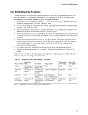
... be displayed before the computer is booted. Password to 16 characters in the BIOS Setup program. This table is for reference only and is set options User Mode Setup Options Can change all None options (Note) Can change a Supervisor Password limited number of options Can change all Enter Password options Clear User Password Can change a Supervisor Password limited number Enter Password of options Note: If no password is entered. • Setting the user password restricts who can enter either the supervisor password or the user password to access Setup...
... be displayed before the computer is booted. Password to 16 characters in the BIOS Setup program. This table is for reference only and is set options User Mode Setup Options Can change all None options (Note) Can change a Supervisor Password limited number of options Can change all Enter Password options Clear User Password Can change a Supervisor Password limited number Enter Password of options Note: If no password is entered. • Setting the user password restricts who can enter either the supervisor password or the user password to access Setup...

Product Specification
Page 88
... a POST card. Reserved for future use (new input console codes). EF boot/S3: resume failure. 88 If the POST fails, execution stops and the last POST code generated is an unrecoverable error. Reserved for future use . Start with PCI. CF D0 - Memory/Chipset: 2F is useful for determining the point where an error occurred. Intel Desktop Board D955XCS Technical Product Specification 4.4 Port 80h POST Codes During the POST, the BIOS generates diagnostic progress codes (POST-codes) to I /O Busses: PCI, USB, ISA...
... a POST card. Reserved for future use (new input console codes). EF boot/S3: resume failure. 88 If the POST fails, execution stops and the last POST code generated is an unrecoverable error. Reserved for future use . Start with PCI. CF D0 - Memory/Chipset: 2F is useful for determining the point where an error occurred. Intel Desktop Board D955XCS Technical Product Specification 4.4 Port 80h POST Codes During the POST, the BIOS generates diagnostic progress codes (POST-codes) to I /O Busses: PCI, USB, ISA...

Product Specification
Page 89
... (including APs) Starting Application processor initialization SMM initialization Chipset Initializing a chipset component Memory Reading SPD from memory DIMMs Detecting presence of memory DIMMs Programming timing parameters in the memory controller and the DIMMs Configuring memory Optimizing memory settings Initializing memory, such as ECC init Testing memory PCI Bus Enumerating PCI busses Allocating resources to PCI bus Hot Plug PCI controller initialization Reserved for PCI Bus USB Resetting USB bus Reserved for USB ATA/ATAPI/SATA Resetting PATA/SATA bus and all devices Reserved for ATA...
... (including APs) Starting Application processor initialization SMM initialization Chipset Initializing a chipset component Memory Reading SPD from memory DIMMs Detecting presence of memory DIMMs Programming timing parameters in the memory controller and the DIMMs Configuring memory Optimizing memory settings Initializing memory, such as ECC init Testing memory PCI Bus Enumerating PCI busses Allocating resources to PCI bus Hot Plug PCI controller initialization Reserved for PCI Bus USB Resetting USB bus Reserved for USB ATA/ATAPI/SATA Resetting PATA/SATA bus and all devices Reserved for ATA...


