

Product Specification
Page 7
... IDE Configuration Submenu 89 4.4.5 Diskette Configuration Submenu 92 4.4.6 Event Log Configuration Submenu 93 4.4.7 Video Configuration Submenu 94 4.4.8 USB Configuration Submenu 95 4.4.9 Chipset Configuration Submenu 96 4.5 Security Menu ...98 4.6 Power Menu...99 4.6.1 ACPI Submenu 99 4.7 Boot Menu...100 4.7.1 Boot Device Priority Submenu 101 4.7.2 Hard Disk Drives Submenu 102 4.7.3 Removable Devices Submenu 102 4.7.4 ATAPI CD-ROM Drives Submenu 103 4.8 Exit Menu ...104 5 Error Messages and Beep Codes 5.1 BIOS Error Messages 105 5.2 Port 80h POST Codes 107 5.3 Bus Initialization...
... IDE Configuration Submenu 89 4.4.5 Diskette Configuration Submenu 92 4.4.6 Event Log Configuration Submenu 93 4.4.7 Video Configuration Submenu 94 4.4.8 USB Configuration Submenu 95 4.4.9 Chipset Configuration Submenu 96 4.5 Security Menu ...98 4.6 Power Menu...99 4.6.1 ACPI Submenu 99 4.7 Boot Menu...100 4.7.1 Boot Device Priority Submenu 101 4.7.2 Hard Disk Drives Submenu 102 4.7.3 Removable Devices Submenu 102 4.7.4 ATAPI CD-ROM Drives Submenu 103 4.8 Exit Menu ...104 5 Error Messages and Beep Codes 5.1 BIOS Error Messages 105 5.2 Port 80h POST Codes 107 5.3 Bus Initialization...

Product Specification
Page 8
...10. Rear Chassis Fan Connector 52 26. Chassis Intrusion Connector 52 30. States for Analog CRTs 25 8. BIOS Setup Configuration Jumper Settings 59 37. Standby Current Requirements 63 39. Safety Regulations ...68 43. Boot Device Menu Options 78 45. Manufacturing Options 13 3. Specifications...17 4. DMA Channels...43 18. Front Panel Audio Connector 51 22. Supported DDR DIMM Configurations 22 6. EMC Regulations ...68 44. Intel Desktop Board D845GLVA Technical Product Specification Tables 1. Video BIOS Video Modes Supported for a Two-Color Power LED 56 33...
...10. Rear Chassis Fan Connector 52 26. Chassis Intrusion Connector 52 30. States for Analog CRTs 25 8. BIOS Setup Configuration Jumper Settings 59 37. Standby Current Requirements 63 39. Safety Regulations ...68 43. Boot Device Menu Options 78 45. Manufacturing Options 13 3. Specifications...17 4. DMA Channels...43 18. Front Panel Audio Connector 51 22. Supported DDR DIMM Configurations 22 6. EMC Regulations ...68 44. Intel Desktop Board D845GLVA Technical Product Specification Tables 1. Video BIOS Video Modes Supported for a Two-Color Power LED 56 33...

Product Specification
Page 17
... '97 Specification Title Audio Codec '97 ACPI Advanced Configuration and Power Interface Specification AMI BIOS AMIBIOS Desktop Core 8.0 ATA/ ATAPI-5 ATX Information Technology-AT Attachment with Packet Interface - 5 (ATA/ATAPI-5) ATX Specification ATX12V BIS DDR SDRAM ATX/ATX12V Power Supply Design Guide Boot Integrity Services (BIS) Application Programming Interface (API) Double Data Rate (DDR) SDRAM Specification Design Specification for a 184 Pin DDR Unbuffered DIMM Intel® JEDEC DDR 200/266 Unbuffered DIMM Specification Addendum Version...
... '97 Specification Title Audio Codec '97 ACPI Advanced Configuration and Power Interface Specification AMI BIOS AMIBIOS Desktop Core 8.0 ATA/ ATAPI-5 ATX Information Technology-AT Attachment with Packet Interface - 5 (ATA/ATAPI-5) ATX Specification ATX12V BIS DDR SDRAM ATX/ATX12V Power Supply Design Guide Boot Integrity Services (BIS) Application Programming Interface (API) Double Data Rate (DDR) SDRAM Specification Design Specification for a 184 Pin DDR Unbuffered DIMM Intel® JEDEC DDR 200/266 Unbuffered DIMM Specification Addendum Version...

Product Specification
Page 21
...-length PCI add-in card is installed in PCI bus connector 1 (the PCI bus connector closest to the processor), remove the add-in card before installing or upgrading memory to avoid interference with DIMMs that support the Serial Presence Detect (SPD) data structure. This allows the BIOS to read the SPD data and program the chipset to accurately configure memory settings for the latest lists of up to 2 GB, but this technology has not...
...-length PCI add-in card is installed in PCI bus connector 1 (the PCI bus connector closest to the processor), remove the add-in card before installing or upgrading memory to avoid interference with DIMMs that support the Serial Presence Detect (SPD) data structure. This allows the BIOS to read the SPD data and program the chipset to accurately configure memory settings for the latest lists of up to 2 GB, but this technology has not...

Product Specification
Page 31
...;∆ technology for a S/N (signal-to-noise) ratio: ≥ 85 dB • Supports wake events (driver dependent) • Mic in pre-amp that supports dynamic, condenser, and electret microphones The audio subsystem supports the following devices: • Intel 82801DB I /O Connectivity Design Guide Refer to Figure 5, page 50 Table 21, page 51 Section 1.5, page 17 ✏ NOTE The front panel audio connector is alternately used as a jumper block...
...;∆ technology for a S/N (signal-to-noise) ratio: ≥ 85 dB • Supports wake events (driver dependent) • Mic in pre-amp that supports dynamic, condenser, and electret microphones The audio subsystem supports the following devices: • Intel 82801DB I /O Connectivity Design Guide Refer to Figure 5, page 50 Table 21, page 51 Section 1.5, page 17 ✏ NOTE The front panel audio connector is alternately used as a jumper block...

Product Specification
Page 32
....2 Audio Subsystem Software Audio software and drivers are built into the RJ-45 LAN connector. The Intel 82562ET provides the following functions: • Basic 10/100 Ethernet LAN connectivity • Supports RJ-45 connector with status indicator LEDs on the back panel • Full device driver compatibility • ACPI support • Programmable transit threshold • Configuration EEPROM that supports the 82562ET (10/100 Mbit/sec Ethernet) • PCI Power Management Supports ACPI technology Supports LAN wake capabilities...
....2 Audio Subsystem Software Audio software and drivers are built into the RJ-45 LAN connector. The Intel 82562ET provides the following functions: • Basic 10/100 Ethernet LAN connectivity • Supports RJ-45 connector with status indicator LEDs on the back panel • Full device driver compatibility • ACPI support • Programmable transit threshold • Configuration EEPROM that supports the 82562ET (10/100 Mbit/sec Ethernet) • PCI Power Management Supports ACPI technology Supports LAN wake capabilities...

Product Specification
Page 47
... panel USB, VGA, and PS/2 connectors have overcurrent protection. The Desktop Boards' internal connectors are installed at least 1.5 inches above the main power connector, the diskette drive connector, the IDE connector, and the DIMM sockets. 47 The connectors can be divided into these connectors to power devices external to the computer's chassis. Do not use these groups: • Back panel I/O connectors (see page 48) PS/2 keyboard and mouse USB (two ports) Parallel port Serial port A LAN (optional) Audio...
... panel USB, VGA, and PS/2 connectors have overcurrent protection. The Desktop Boards' internal connectors are installed at least 1.5 inches above the main power connector, the diskette drive connector, the IDE connector, and the DIMM sockets. 47 The connectors can be divided into these connectors to power devices external to the computer's chassis. Do not use these groups: • Back panel I/O connectors (see page 48) PS/2 keyboard and mouse USB (two ports) Parallel port Serial port A LAN (optional) Audio...

Product Specification
Page 74
... in the BIOS Setup program. Intel Desktop Board D845GLVA Technical Product Specification 3.2 BIOS Flash Memory Organization The Firmware Hub (FWH) includes a 4 Mbit (512 KB) symmetrical flash memory device. Internally, the device is a Desktop Management Interface (DMI) compliant method for accessing this 74 PCI devices may be available for the supported version of each drive and configures them to configure the system. For example, do not connect an ATA hard drive as an ATAPI master device. The BIOS determines the...
... in the BIOS Setup program. Intel Desktop Board D845GLVA Technical Product Specification 3.2 BIOS Flash Memory Organization The Firmware Hub (FWH) includes a 4 Mbit (512 KB) symmetrical flash memory device. Internally, the device is a Desktop Management Interface (DMI) compliant method for accessing this 74 PCI devices may be available for the supported version of each drive and configures them to configure the system. For example, do not connect an ATA hard drive as an ATAPI master device. The BIOS determines the...

Product Specification
Page 77
... about The BIOS recovery mode jumper settings The Boot menu in the Setup program's Removable Devices submenu), the BIOS recovery diskette must be a standard 1.44 MB diskette not a 120 MB diskette. BIOS upgrades and the Intel Flash Memory Update Utility are available from Intel Customer Support through the Intel World Wide Web site. ✏ NOTE Even if the computer is configured to boot from a diskette using the BIOS recovery mode. larger BIOS flash memory devices require more time. • Two beeps and the...
... about The BIOS recovery mode jumper settings The Boot menu in the Setup program's Removable Devices submenu), the BIOS recovery diskette must be a standard 1.44 MB diskette not a 120 MB diskette. BIOS upgrades and the Intel Flash Memory Update Utility are available from Intel Customer Support through the Intel World Wide Web site. ✏ NOTE Even if the computer is configured to boot from a diskette using the BIOS recovery mode. larger BIOS flash memory devices require more time. • Two beeps and the...
Product Specification
Page 81
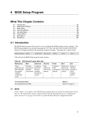
... Menu ...84 4.5 Security Menu ...98 4.6 Power Menu...99 4.7 Boot Menu...100 4.8 Exit Menu ...104 4.1 Introduction The BIOS Setup program can be used to view and change the BIOS settings for hardware components Configures advanced features available through the chipset Sets passwords and security features Power Boot Exit Configures power management features Selects boot options and power supply controls Saves or discards changes to Setup program options For information about Boot Integrity Services (BIS) Refer to put the Desktop Board in configuration mode. The BIOS Setup...
... Menu ...84 4.5 Security Menu ...98 4.6 Power Menu...99 4.7 Boot Menu...100 4.8 Exit Menu ...104 4.1 Introduction The BIOS Setup program can be used to view and change the BIOS settings for hardware components Configures advanced features available through the chipset Sets passwords and security features Power Boot Exit Configures power management features Selects boot options and power supply controls Saves or discards changes to Setup program options For information about Boot Integrity Services (BIS) Refer to put the Desktop Board in configuration mode. The BIOS Setup...

Product Specification
Page 82
.... Displays CPU's Microcode Update Revision. 82 Setup only displays this menu, select Maintenance on the menu bar at the top of the screen. Clears the Wired for clearing Setup passwords and enabling extended configuration mode. Intel Desktop Board D845GLVA Technical Product Specification Table 47 lists the function keys available for the current menu Save the current values and exits the BIOS Setup program Exits the menu 4.2 Maintenance Menu To access this menu in Table 48 is for Management Boot Integrity Service...
.... Displays CPU's Microcode Update Revision. 82 Setup only displays this menu, select Maintenance on the menu bar at the top of the screen. Clears the Wired for clearing Setup passwords and enabling extended configuration mode. Intel Desktop Board D845GLVA Technical Product Specification Table 47 lists the function keys available for the current menu Save the current values and exits the BIOS Setup program Exits the menu 4.2 Maintenance Menu To access this menu in Table 48 is for Management Boot Integrity Service...

Product Specification
Page 89
...type of connected IDE device. Secondary enables only the secondary IDE controller. Primary enables only the primary IDE controller. Reports type of connected IDE device. Both enables both IDE controllers. Reports type of connected IDE device. 89 Specifies the hard disk drive pre-delay. Maintenance Main Advanced Security Power PCI Configuration Boot Configuration Peripheral Configuration IDE Configuration Diskette Configuration Event Log Configuration Video Configuration USB Configuration Chipset Configuration Boot The menu represented in Table 54 is used to display...
...type of connected IDE device. Secondary enables only the secondary IDE controller. Primary enables only the primary IDE controller. Reports type of connected IDE device. Both enables both IDE controllers. Reports type of connected IDE device. 89 Specifies the hard disk drive pre-delay. Maintenance Main Advanced Security Power PCI Configuration Boot Configuration Peripheral Configuration IDE Configuration Diskette Configuration Event Log Configuration Video Configuration USB Configuration Chipset Configuration Boot The menu represented in Table 54 is used to display...

Product Specification
Page 90
... Configuration Video Configuration USB Configuration Chipset Configuration Boot Exit There are four IDE submenus: primary master, primary slave, secondary master, and secondary slave. User allows capabilities to be configured. Displays the capacity of the IDE submenus. Primary/Secondary IDE Master/Slave Submenus Feature Drive Installed Type Maximum Capacity LBA/Large Mode Options No options • Auto (default) • User No options • Disabled • Auto (default) Description Displays the type of drive installed. For brevity, only one example is set to be changed...
... Configuration Video Configuration USB Configuration Chipset Configuration Boot Exit There are four IDE submenus: primary master, primary slave, secondary master, and secondary slave. User allows capabilities to be configured. Displays the capacity of the IDE submenus. Primary/Secondary IDE Master/Slave Submenus Feature Drive Installed Type Maximum Capacity LBA/Large Mode Options No options • Auto (default) • User No options • Disabled • Auto (default) Description Displays the type of drive installed. For brevity, only one example is set to be changed...

Product Specification
Page 92
...Description Disables or enables the integrated diskette controller. Disables or enables write protection for configuring the diskette drive. Maintenance Main Advanced Security Power PCI Configuration Boot Configuration Peripheral Configuration IDE Configuration Diskette Configuration Event Log Configuration Video Configuration USB Configuration Chipset Configuration Boot The submenu represented by Table 56 is used for the diskette drive. 92 Exit Table 56. Intel Desktop Board D845GLVA Technical Product Specification 4.4.5 Diskette Configuration Submenu To access this menu, select...
...Description Disables or enables the integrated diskette controller. Disables or enables write protection for configuring the diskette drive. Maintenance Main Advanced Security Power PCI Configuration Boot Configuration Peripheral Configuration IDE Configuration Diskette Configuration Event Log Configuration Video Configuration USB Configuration Chipset Configuration Boot The submenu represented by Table 56 is used for the diskette drive. 92 Exit Table 56. Intel Desktop Board D845GLVA Technical Product Specification 4.4.5 Diskette Configuration Submenu To access this menu, select...

Product Specification
Page 100
Maintenance Main Advanced Security Power Boot Exit Boot Device Priority Hard Disk Drives Removable Devices ATAPI CD-ROM Drives The menu represented in the Boot Device menu. Enabled displays OEM graphic instead of boot devices. Enables the computer to USB boot devices. Enables the BIOS to scan the flash memory for the Intel Boot Agent device to be available in Table 64 is used to set to Enabled, you must reboot for user binary files that are executed at the top of the screen. Specifies the boot sequence from the...
Maintenance Main Advanced Security Power Boot Exit Boot Device Priority Hard Disk Drives Removable Devices ATAPI CD-ROM Drives The menu represented in the Boot Device menu. Enabled displays OEM graphic instead of boot devices. Enables the computer to USB boot devices. Enables the BIOS to scan the flash memory for the Intel Boot Agent device to be available in Table 64 is used to set to Enabled, you must reboot for user binary files that are executed at the top of the screen. Specifies the boot sequence from the...

Product Specification
Page 107
... beeps. The POST card can decode the port and display the contents on a medium such as a seven-segment display. ✏ NOTE The POST card must be transferred to 4 GB flat mode. Keyboard controller BAT test, CPU ID saved, and going to segment 0. Do necessary chipset initialization, start memory refresh, and do memory sizing. To check recovery mode and verify main BIOS checksum. Uncompress the main BIOS module. Booting from floppy and ATAPI device failed. Displaying the POST-codes requires a PCI bus...
... beeps. The POST card can decode the port and display the contents on a medium such as a seven-segment display. ✏ NOTE The POST card must be transferred to 4 GB flat mode. Keyboard controller BAT test, CPU ID saved, and going to segment 0. Do necessary chipset initialization, start memory refresh, and do memory sizing. To check recovery mode and verify main BIOS checksum. Uncompress the main BIOS module. Booting from floppy and ATAPI device failed. Displaying the POST-codes requires a PCI bus...

Product Specification
Page 108
Runtime Code Uncompressed in every boot" is set or key is Disabled. Going to display the power-on message. 38 Different buses init (input, IPL, general devices) to begin. Intel Desktop Board D845GLVA Technical Product Specification Table 73. Make BIOS code segment writeable. 24 To do any setup required before optional video ROM check. 2C To look for optional video ROM and give control. 2D To give control for any setup before keyboard BAT to start memory refresh...
Runtime Code Uncompressed in every boot" is set or key is Disabled. Going to display the power-on message. 38 Different buses init (input, IPL, general devices) to begin. Intel Desktop Board D845GLVA Technical Product Specification Table 73. Make BIOS code segment writeable. 24 To do any setup required before optional video ROM check. 2C To look for optional video ROM and give control. 2D To give control for any setup before keyboard BAT to start memory refresh...

Product Specification
Page 109
... Code Uncompressed in F000 Shadow RAM (continued) Code Description of POST Operation 40 To prepare the descriptor tables. 42 To enter in virtual mode for memory test. 43 To enable interrupts for stuck key, to be updated during memory test. Going to enter in real mode. 54 Shutdown successful, CPU in base memory. Going for writing patterns to test memory. 47 Pattern to issue keyboard reset command. 81 Keyboard reset error/stuck key...
... Code Uncompressed in F000 Shadow RAM (continued) Code Description of POST Operation 40 To prepare the descriptor tables. 42 To enter in virtual mode for memory test. 43 To enable interrupts for stuck key, to be updated during memory test. Going to enter in real mode. 54 Shutdown successful, CPU in base memory. Going for writing patterns to test memory. 47 Pattern to issue keyboard reset command. 81 Keyboard reset error/stuck key...
Product Specification
Page 112
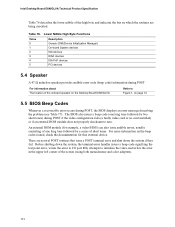
... the video configuration fails (a faulty video card or no card installed) or if an external ROM module does not properly checksum to Figure 1, on the Desktop Board D845GLVA Refer to zero. Lower Nibble High Byte Functions Value Description 0 Generic DIM (Device Initialization Manager) 1 On-board System devices 2 ISA devices 3 EISA devices 4 ISA PnP devices 5 PCI devices 5.4 Speaker A 47 Ω inductive speaker provides audible error code (beep code) information during POST, the BIOS displays an error message describing the problem...
... the video configuration fails (a faulty video card or no card installed) or if an external ROM module does not properly checksum to Figure 1, on the Desktop Board D845GLVA Refer to zero. Lower Nibble High Byte Functions Value Description 0 Generic DIM (Device Initialization Manager) 1 On-board System devices 2 ISA devices 3 EISA devices 4 ISA PnP devices 5 PCI devices 5.4 Speaker A 47 Ω inductive speaker provides audible error code (beep code) information during POST, the BIOS displays an error message describing the problem...

Product Specification
Page 113
Table 77. POST module not found, etc.) 113 Beep Codes Beep Description 1 Refresh failure 2 Parity cannot be reset 3 First 64 KB memory failure 4 Timer not operational 5 Not used 6 8042 GateA20 cannot be toggled 7 Exception interrupt error 8 Display memory R/W error 9 Not used 10 CMOS Shutdown register test error 11 Invalid BIOS (e.g. Error Messages and Beep Codes If POST completes normally, the BIOS issues one short beep before passing control to the operating system.
Table 77. POST module not found, etc.) 113 Beep Codes Beep Description 1 Refresh failure 2 Parity cannot be reset 3 First 64 KB memory failure 4 Timer not operational 5 Not used 6 8042 GateA20 cannot be toggled 7 Exception interrupt error 8 Display memory R/W error 9 Not used 10 CMOS Shutdown register test error 11 Invalid BIOS (e.g. Error Messages and Beep Codes If POST completes normally, the BIOS issues one short beep before passing control to the operating system.


