
Product Guide
Page 3
... Technology Equipment (I.T.E.) for use in personal computers (PC) for installation in this manual: CAUTION Cautions warn the user about how to prevent damage to hardware or loss of data. The suitability of product features 2 Installing and Replacing Desktop Board Components: instructions on how to install the Desktop Board and other hardware components 3 Updating the BIOS: instructions on how to update the BIOS A Error Messages and Indicators: information about board layout, component installation, BIOS update...
... Technology Equipment (I.T.E.) for use in personal computers (PC) for installation in this manual: CAUTION Cautions warn the user about how to prevent damage to hardware or loss of data. The suitability of product features 2 Installing and Replacing Desktop Board Components: instructions on how to install the Desktop Board and other hardware components 3 Updating the BIOS: instructions on how to update the BIOS A Error Messages and Indicators: information about board layout, component installation, BIOS update...
Product Guide
Page 5
...15 Main Memory...15 Graphics Subsystem 15 Integrated Graphics 15 Intel® HD Graphics 16 High-Definition Multimedia Interface* (HDMI 16 Digital Visual Interface (DVI-I 16 VGA Displays 16 PCI Express* x16 Graphics 17 Audio Subsystem 17 LAN Subsystem 18 USB Support ...19 SATA Support...19 Expandability...19 Legacy I/O ...20 BIOS ...20 SATA Auto Configuration 20 PCI*/PCI Express Auto Configuration 20 Security Passwords 21 Hardware Management 21 Hardware Monitoring and Fan Speed Control 21 Fan Monitoring 21 Chassis Intrusion 22 Power Management 22 Software Support 22 ACPI 22...
...15 Main Memory...15 Graphics Subsystem 15 Integrated Graphics 15 Intel® HD Graphics 16 High-Definition Multimedia Interface* (HDMI 16 Digital Visual Interface (DVI-I 16 VGA Displays 16 PCI Express* x16 Graphics 17 Audio Subsystem 17 LAN Subsystem 18 USB Support ...19 SATA Support...19 Expandability...19 Legacy I/O ...20 BIOS ...20 SATA Auto Configuration 20 PCI*/PCI Express Auto Configuration 20 Security Passwords 21 Hardware Management 21 Hardware Monitoring and Fan Speed Control 21 Fan Monitoring 21 Chassis Intrusion 22 Power Management 22 Software Support 22 ACPI 22...
Product Guide
Page 6
... a PCI Express x16 Graphics Card 42 Connecting SATA Drives 43 Connecting to the Internal Headers 44 Front Panel Audio Header 45 Chassis Intrusion Header 45 Consumer IR (CIR) Headers 46 Alternate Front Panel Power LED Header 47 Front Panel Header 47 Front Panel USB 2.0 Headers 48 S/PDIF Header 48 Connecting to the Audio System 49 Connecting Chassis Fan and Power Supply Cables 50 Connecting a Chassis Fan 50 Connecting Power Supply Cables 51 Setting the BIOS Configuration Jumper 52 Clearing Passwords 53 Replacing the Battery 54 3 Updating the BIOS Updating the BIOS with the Intel...
... a PCI Express x16 Graphics Card 42 Connecting SATA Drives 43 Connecting to the Internal Headers 44 Front Panel Audio Header 45 Chassis Intrusion Header 45 Consumer IR (CIR) Headers 46 Alternate Front Panel Power LED Header 47 Front Panel Header 47 Front Panel USB 2.0 Headers 48 S/PDIF Header 48 Connecting to the Audio System 49 Connecting Chassis Fan and Power Supply Cables 50 Connecting a Chassis Fan 50 Connecting Power Supply Cables 51 Setting the BIOS Configuration Jumper 52 Clearing Passwords 53 Replacing the Battery 54 3 Updating the BIOS Updating the BIOS with the Intel...

Product Guide
Page 7
LAN Connector LEDs 18 3. Intel Desktop Board DH67BL Mounting Screw Hole Locations 30 6. Install the Processor 33 10. Example Dual Channel Memory Configuration with Three DIMMs 37 15. Installing a DIMM 39 17. Internal Headers 44 21. Location of the Chassis Fan Header 50 23. Intel Desktop Board DH67BL China RoHS Material Self Declaration Table 72 vii Installing the I/O Shield 29 5. Connecting the Processor Fan Heat Sink Power Cable to the Processor Fan Header.35 12. Connecting a SATA Drive 43 20. Connecting Power Supply Cables 51 24. Lift the Load Plate 32...
LAN Connector LEDs 18 3. Intel Desktop Board DH67BL Mounting Screw Hole Locations 30 6. Install the Processor 33 10. Example Dual Channel Memory Configuration with Three DIMMs 37 15. Installing a DIMM 39 17. Internal Headers 44 21. Location of the Chassis Fan Header 50 23. Intel Desktop Board DH67BL China RoHS Material Self Declaration Table 72 vii Installing the I/O Shield 29 5. Connecting the Processor Fan Heat Sink Power Cable to the Processor Fan Header.35 12. Connecting a SATA Drive 43 20. Connecting Power Supply Cables 51 24. Lift the Load Plate 32...

Product Guide
Page 8
.... USB 2.0 Header Signal Names 48 13. BIOS Beep Codes 65 16. LAN Connector LEDs 19 5. S/PDIF Header Signal Names 48 14. Audio Jack Retasking Support 18 4. Front Panel Audio Signal Names for AC '97 Audio 45 7. Front Panel Header Signal Names 47 12. Front-panel Power LED Blink Codes 66 17. Alternate Front Panel Power LED Header Signal Names 47 11. EMC Regulations 73 20. Regulatory Compliance Marks 76 viii Intel Desktop Board DH67BL Product Guide Tables 1. Jumper Settings for...
.... USB 2.0 Header Signal Names 48 13. BIOS Beep Codes 65 16. LAN Connector LEDs 19 5. S/PDIF Header Signal Names 48 14. Audio Jack Retasking Support 18 4. Front Panel Audio Signal Names for AC '97 Audio 45 7. Front Panel Header Signal Names 47 12. Front-panel Power LED Blink Codes 66 17. Alternate Front Panel Power LED Header Signal Names 47 11. EMC Regulations 73 20. Regulatory Compliance Marks 76 viii Intel Desktop Board DH67BL Product Guide Tables 1. Jumper Settings for...
Product Guide
Page 10
... LAN controller including an RJ-45 back panel connector with integrated status LEDs • Intel® BIOS resident in an SPI Flash device • Support for Advanced Configuration and Power Interface (ACPI), Plug and Play, and SMBIOS • BIOS support for Hyper Boot • UEFI to support hard disk drives larger than 2 TB Instantly Available PC Technology • Support for PCI Local Bus Specification Revision 2.3 • Support for PCI Express Base Specification Revision 2.0 • Suspend to RAM support • Wake on PCI Express, LAN, front panel, CIR, and USB ports...
... LAN controller including an RJ-45 back panel connector with integrated status LEDs • Intel® BIOS resident in an SPI Flash device • Support for Advanced Configuration and Power Interface (ACPI), Plug and Play, and SMBIOS • BIOS support for Hyper Boot • UEFI to support hard disk drives larger than 2 TB Instantly Available PC Technology • Support for PCI Local Bus Specification Revision 2.3 • Support for PCI Express Base Specification Revision 2.0 • Suspend to RAM support • Wake on PCI Express, LAN, front panel, CIR, and USB ports...
Product Guide
Page 15
... board should be populated with Intel HD 2000 and 3000 Graphics. 15 The BIOS will attempt to the processor and the USB, SATA, LPC, audio, network, display, and PCI Express x1 interfaces. Graphics Subsystem The board supports system graphics through the Intel® Flexible Display Interface (Intel® FDI) for processors with DIMMs that support the Serial Presence Detect (SPD) data structure. Integrated Graphics The board supports integrated graphics through either Intel HD Graphics or a PCI Express 2.0 x16 add-in graphics card...
... board should be populated with Intel HD 2000 and 3000 Graphics. 15 The BIOS will attempt to the processor and the USB, SATA, LPC, audio, network, display, and PCI Express x1 interfaces. Graphics Subsystem The board supports system graphics through the Intel® Flexible Display Interface (Intel® FDI) for processors with DIMMs that support the Serial Presence Detect (SPD) data structure. Integrated Graphics The board supports integrated graphics through either Intel HD Graphics or a PCI Express 2.0 x16 add-in graphics card...

Product Guide
Page 20
...; Serial IRQ interface compatible with serialized IRQ support for PCI Conventional bus systems • Intelligent power management, including a programmable wake-up event interface The BIOS Setup program provides configuration options for the Legacy I /O space) for your computer, the PCI Express autoconfiguration utility in card. 20 You can be updated by specifying manual configuration in the BIOS Setup program. Intel Desktop Board DH67BL Product Guide Legacy I/O The board's Legacy I/O Controller provides the following the instructions in Chapter 3 starting on page 61. BIOS The BIOS...
...; Serial IRQ interface compatible with serialized IRQ support for PCI Conventional bus systems • Intelligent power management, including a programmable wake-up event interface The BIOS Setup program provides configuration options for the Legacy I /O space) for your computer, the PCI Express autoconfiguration utility in card. 20 You can be updated by specifying manual configuration in the BIOS Setup program. Intel Desktop Board DH67BL Product Guide Legacy I/O The board's Legacy I/O Controller provides the following the instructions in Chapter 3 starting on page 61. BIOS The BIOS...

Product Guide
Page 21
... the password prompt of Intel Desktop Board DH67BL enable the board to access Setup. For instructions on resetting the password, go to boot the computer. Fan Monitoring Fan monitoring can be compatible with the following : • Fan speed monitoring and control • Thermal and voltage monitoring • Chassis intrusion detection Hardware Monitoring and Fan Speed Control The features of system voltages to view and change all fans that restrict whether the BIOS Setup program can be set for the BIOS Setup and for viewing and changing depending...
... the password prompt of Intel Desktop Board DH67BL enable the board to access Setup. For instructions on resetting the password, go to boot the computer. Fan Monitoring Fan monitoring can be compatible with the following : • Fan speed monitoring and control • Thermal and voltage monitoring • Chassis intrusion detection Hardware Monitoring and Fan Speed Control The features of system voltages to view and change all fans that restrict whether the BIOS Setup program can be set for the BIOS Setup and for viewing and changing depending...

Product Guide
Page 22
...; +5 V standby power indicator LED • Wake from USB • PCI Express WAKE# signal support • Wake from an AC power failure, the computer returns to the chassis intrusion header on the chassis that provides full ACPI support. Intel Desktop Board DH67BL Product Guide Chassis Intrusion The board supports a chassis security feature that detects if the chassis cover has been removed. The computer's response can be set by using the Last Power State feature in before power was in the BIOS Setup program's Boot menu.
...; +5 V standby power indicator LED • Wake from USB • PCI Express WAKE# signal support • Wake from an AC power failure, the computer returns to the chassis intrusion header on the chassis that provides full ACPI support. Intel Desktop Board DH67BL Product Guide Chassis Intrusion The board supports a chassis security feature that detects if the chassis cover has been removed. The computer's response can be set by using the Last Power State feature in before power was in the BIOS Setup program's Boot menu.

Product Guide
Page 23
... the computer is in the ACPI S0 or S1 state. • The fans are controlled by Pulse Width Modulation. • The chassis fan header supports linear fan control on 3-wire fans. LAN Wake Capabilities CAUTION For LAN wake capabilities, the 5 V standby line for the power supply must be capable of delivering adequate +5 V standby current. When signaled by the BIOS "S3 State Indicator" option). The Desktop Board has a 4-pin processor fan header and two 4-pin chassis fan headers compatible with 4-wire and 3-wire chassis fans.
... the computer is in the ACPI S0 or S1 state. • The fans are controlled by Pulse Width Modulation. • The chassis fan header supports linear fan control on 3-wire fans. LAN Wake Capabilities CAUTION For LAN wake capabilities, the 5 V standby line for the power supply must be capable of delivering adequate +5 V standby current. When signaled by the BIOS "S3 State Indicator" option). The Desktop Board has a 4-pin processor fan header and two 4-pin chassis fan headers compatible with 4-wire and 3-wire chassis fans.

Product Guide
Page 25
... plugged in, the standby current from USB. The clock is mounted on standby current requirements for instructions on a PCI Express bus add-in CMOS RAM (for a description of the battery. Refer to ± 13 minutes/year at http://support.intel.com/support/motherboards/desktop/ Wake from USB NOTE Wake from USB requires the use of a USB peripheral that supports Wake from USB and an operating system that supports Wake from the power supply extends the life of the board's beep codes. Speaker A speaker...
... plugged in, the standby current from USB. The clock is mounted on standby current requirements for instructions on a PCI Express bus add-in CMOS RAM (for a description of the battery. Refer to ± 13 minutes/year at http://support.intel.com/support/motherboards/desktop/ Wake from USB NOTE Wake from USB requires the use of a USB peripheral that supports Wake from USB and an operating system that supports Wake from the power supply extends the life of the board's beep codes. Speaker A speaker...

Product Guide
Page 27
... though the front panel power button is off. 2 Installing and Replacing Desktop Board Components This chapter tells you how to: • Install the I/O shield • Install and remove the Desktop Board • Install and remove a processor • Install and remove memory • Install and remove a PCI Express x16 card • Connect SATA drives • Connect to the internal headers • Connect to the audio system • Connect chassis fan and power supply cables • Set the BIOS configuration jumper • Clear passwords • Replace the battery Before You Begin...
... though the front panel power button is off. 2 Installing and Replacing Desktop Board Components This chapter tells you how to: • Install the I/O shield • Install and remove the Desktop Board • Install and remove a processor • Install and remove memory • Install and remove a PCI Express x16 card • Connect SATA drives • Connect to the internal headers • Connect to the audio system • Connect chassis fan and power supply cables • Set the BIOS configuration jumper • Clear passwords • Replace the battery Before You Begin...

Product Guide
Page 39
... removed in the PCI Express x16 connector, remove the card to gain full access to the computer. Turn off the computer and disconnect the AC power cord. 3. Insert the bottom edge of the DIMM until the retaining clips snap into the socket. 9. Position the DIMM above the socket. If a full length PCI Express graphics card is inserted, push down on page 27. 2. Installing and Replacing Desktop Board Components To install...
... removed in the PCI Express x16 connector, remove the card to gain full access to the computer. Turn off the computer and disconnect the AC power cord. 3. Insert the bottom edge of the DIMM until the retaining clips snap into the socket. 9. Position the DIMM above the socket. If a full length PCI Express graphics card is inserted, push down on page 27. 2. Installing and Replacing Desktop Board Components To install...

Product Guide
Page 40
... across the connector pins. Depending on the system. Turn off all peripheral devices connected to reach the DIMMs. 9. If a full length PCI Express graphics card is installed in Step 5 and reconnect any other parts you power on the over-current protection of the power supply, certain Desktop Board components and/or traces may be damaged by the edges, lift it in the connector, an electrical short may be...
... across the connector pins. Depending on the system. Turn off all peripheral devices connected to reach the DIMMs. 9. If a full length PCI Express graphics card is installed in Step 5 and reconnect any other parts you power on the over-current protection of the power supply, certain Desktop Board components and/or traces may be damaged by the edges, lift it in the connector, an electrical short may be...

Product Guide
Page 50
Figure 22 shows the location of the Chassis Fan Header 50 Location of the chassis fan header. Figure 22. Intel Desktop Board DH67BL Product Guide Connecting Chassis Fan and Power Supply Cables Connecting a Chassis Fan Connect the chassis fan cable to the chassis fan header on the Desktop Board.
Figure 22 shows the location of the Chassis Fan Header 50 Location of the chassis fan header. Figure 22. Intel Desktop Board DH67BL Product Guide Connecting Chassis Fan and Power Supply Cables Connecting a Chassis Fan Connect the chassis fan cable to the chassis fan header on the Desktop Board.
Product Guide
Page 53
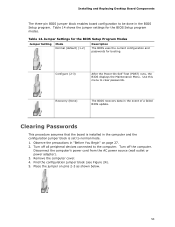
... power adapter). 3. Table 14 shows the jumper settings for booting. Observe the precautions in the event of a failed BIOS update. Find the configuration jumper block (see Figure 24). 5. Remove the computer cover. 4. Place the jumper on page 27. 2. Installing and Replacing Desktop Board Components The three-pin BIOS jumper block enables board configuration to normal mode. 1. Turn off all peripheral devices connected to clear passwords. Use this menu to the computer. Jumper Settings for the BIOS Setup Program Modes Jumper Setting Mode Normal (default) (1-2) Description...
... power adapter). 3. Table 14 shows the jumper settings for booting. Observe the precautions in the event of a failed BIOS update. Find the configuration jumper block (see Figure 24). 5. Remove the computer cover. 4. Place the jumper on page 27. 2. Installing and Replacing Desktop Board Components The three-pin BIOS jumper block enables board configuration to normal mode. 1. Turn off all peripheral devices connected to clear passwords. Use this menu to the computer. Jumper Settings for the BIOS Setup Program Modes Jumper Setting Mode Normal (default) (1-2) Description...
Product Guide
Page 54
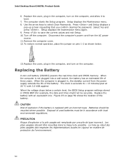
... years. Press and Setup displays a pop-up screen requesting that you confirm clearing the password. To restore normal operation, place the jumper on page 59 shows the location of the battery. Remove the computer cover. 12. Replace the cover, plug in , the standby current from the AC power source. 11. When the voltage drops below . 13. Setup displays the Maintenance menu. 8. Setup displays the maintenance menu again. 9. When the...
... years. Press and Setup displays a pop-up screen requesting that you confirm clearing the password. To restore normal operation, place the jumper on page 59 shows the location of the battery. Remove the computer cover. 12. Replace the cover, plug in , the standby current from the AC power source. 11. When the voltage drops below . 13. Setup displays the Maintenance menu. 8. Setup displays the maintenance menu again. 9. When the...
Product Guide
Page 61
... of the Intel Flash Memory Update Utility and the ease of use of Windows-based installation wizards. Navigate to a removable USB device. To update the BIOS with the Intel® Express BIOS Update Utility With the Intel Express BIOS Update utility you how to update the BIOS by pressing the key after the Power-On Self-Test (POST) memory test begins and before the operating system boot begins. The BIOS file is required. Double-click the executable file from the location on the "BIOS Update" link...
... of the Intel Flash Memory Update Utility and the ease of use of Windows-based installation wizards. Navigate to a removable USB device. To update the BIOS with the Intel® Express BIOS Update Utility With the Intel Express BIOS Update utility you how to update the BIOS by pressing the key after the Power-On Self-Test (POST) memory test begins and before the operating system boot begins. The BIOS file is required. Double-click the executable file from the location on the "BIOS Update" link...

Product Guide
Page 64
... about updating the Intel Desktop Board BIOS or recovering from the hard drive if no key is pressed within 15 seconds. 5. Follow these instructions to the Intel Desktop Board DH67BL page on the "BIOS Update" link and then select the Recovery BIOS Update file. You can obtain the Recovery BIOS Update file through your computer supplier or by navigating to upgrade the BIOS using the ISO Image BIOS file: 1. Insert the CD that anything will boot from a BIOS update failure, go...
... about updating the Intel Desktop Board BIOS or recovering from the hard drive if no key is pressed within 15 seconds. 5. Follow these instructions to the Intel Desktop Board DH67BL page on the "BIOS Update" link and then select the Recovery BIOS Update file. You can obtain the Recovery BIOS Update file through your computer supplier or by navigating to upgrade the BIOS using the ISO Image BIOS file: 1. Insert the CD that anything will boot from a BIOS update failure, go...


