Product Specification
Page 5
... Description 1.1 Overview 9 1.1.1 Feature Summary 9 1.1.2 Board Layout 11 1.1.3 Block Diagram 13 1.2 Legacy Considerations 14 1.3 Online Support 14 1.4 Processor 14 1.5 System Memory 15 1.6 Intel® 945GC Chipset 16 1.6.1 Intel 945GC Graphics Subsystem 16 1.6.2 USB 18 1.6.3 IDE Support 18 1.7 Real-Time Clock Subsystem 19 1.8 S-Video Output 20 1.9 Legacy I/O Controller 20 1.9.1 Serial Port 20 1.9.2 Parallel Port 20...
... Description 1.1 Overview 9 1.1.1 Feature Summary 9 1.1.2 Board Layout 11 1.1.3 Block Diagram 13 1.2 Legacy Considerations 14 1.3 Online Support 14 1.4 Processor 14 1.5 System Memory 15 1.6 Intel® 945GC Chipset 16 1.6.1 Intel 945GC Graphics Subsystem 16 1.6.2 USB 18 1.6.3 IDE Support 18 1.7 Real-Time Clock Subsystem 19 1.8 S-Video Output 20 1.9 Legacy I/O Controller 20 1.9.1 Serial Port 20 1.9.2 Parallel Port 20...
Product Specification
Page 6
Intel Desktop Board D945GCLF2 Technical Product Specification 2.5.1 Power Supply Considerations 51 2.5.2 Fan Header Current Capability 51 2.5.3 Add-in Board Considerations 52 2.6 Thermal Considerations 52 2.7 Reliability 54 2.8 Environmental 54 3 Overview of BIOS Features 3.1 Introduction 55 3.2 BIOS Flash Memory Organization 56 3.3 Resource Configuration 56 3.3.1 PCI* Autoconfiguration 56 3.4 System Management BIOS (SMBIOS 57 3.5 Legacy USB Support...
Intel Desktop Board D945GCLF2 Technical Product Specification 2.5.1 Power Supply Considerations 51 2.5.2 Fan Header Current Capability 51 2.5.3 Add-in Board Considerations 52 2.6 Thermal Considerations 52 2.7 Reliability 54 2.8 Environmental 54 3 Overview of BIOS Features 3.1 Introduction 55 3.2 BIOS Flash Memory Organization 56 3.3 Resource Configuration 56 3.3.1 PCI* Autoconfiguration 56 3.4 System Management BIOS (SMBIOS 57 3.5 Legacy USB Support...
Product Specification
Page 7
... Header 46 11. LAN Connector LED States 25 6. Rear Chassis (3-Pin) Fan Header 44 14. Contents Figures 1. Connection Diagram for Front Panel USB Headers 48 12. Location of the Standby Power Indicator LED 35 7. Board Dimensions 50 14. Supported Memory Configurations 15 4. Audio Jack Retasking Support ... 1 12 3. BIOS Setup Program Menu Bar 56 27. Detailed System Memory Address Map 38 8. States for Components 53 25. Intel Desktop Board D945GCLF2 Environmental Specifications 54 26. Front Panel Header 46 19. Component-side Connectors and Headers 42 10.
... Header 46 11. LAN Connector LED States 25 6. Rear Chassis (3-Pin) Fan Header 44 14. Contents Figures 1. Connection Diagram for Front Panel USB Headers 48 12. Location of the Standby Power Indicator LED 35 7. Board Dimensions 50 14. Supported Memory Configurations 15 4. Audio Jack Retasking Support ... 1 12 3. BIOS Setup Program Menu Bar 56 27. Detailed System Memory Address Map 38 8. States for Components 53 25. Intel Desktop Board D945GCLF2 Environmental Specifications 54 26. Front Panel Header 46 19. Component-side Connectors and Headers 42 10.
Product Specification
Page 9
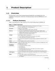
...by 6.75 inches [171.45 millimeters by 171.45 millimeters]) Processor Memory Chipset Support for the following: • Soldered-down Dual-Core Intel® Atom® processor • One 240-pin DDR2 SDRAM Dual Inline Memory Module (DIMM) socket • Support for DDR2 533... Table 1 summarizes the major features of the Intel Desktop Board D945GCLF2. Table 1. For readability, the document references the board product name as D945GCLF2 in the SPI Flash device) • Support for hardware management, serial, parallel, and PS/2* ports • Eight USB 2.0 ports • Two Serial ATA (SATA...
...by 6.75 inches [171.45 millimeters by 171.45 millimeters]) Processor Memory Chipset Support for the following: • Soldered-down Dual-Core Intel® Atom® processor • One 240-pin DDR2 SDRAM Dual Inline Memory Module (DIMM) socket • Support for DDR2 533... Table 1 summarizes the major features of the Intel Desktop Board D945GCLF2. Table 1. For readability, the document references the board product name as D945GCLF2 in the SPI Flash device) • Support for hardware management, serial, parallel, and PS/2* ports • Eight USB 2.0 ports • Two Serial ATA (SATA...
Product Specification
Page 10
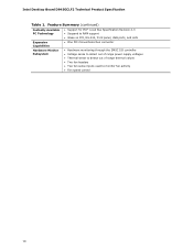
... Capabilities Hardware Monitor Subsystem • Support for PCI* Local Bus Specification Revision 2.3 • Suspend to RAM support • Wake on PCI, RS-232, front panel, USB ports, and LAN • One PCI Conventional bus connector • Hardware monitoring through the SMSC I/O controller • Voltage sense to detect out of range power... detect out of range thermal values • Two fan headers • Two fan sense inputs used to monitor fan activity • Fan speed control 10 Intel Desktop Board D945GCLF2 Technical Product Specification Table 1.
... Capabilities Hardware Monitor Subsystem • Support for PCI* Local Bus Specification Revision 2.3 • Suspend to RAM support • Wake on PCI, RS-232, front panel, USB ports, and LAN • One PCI Conventional bus connector • Hardware monitoring through the SMSC I/O controller • Voltage sense to detect out of range power... detect out of range thermal values • Two fan headers • Two fan sense inputs used to monitor fan activity • Fan speed control 10 Intel Desktop Board D945GCLF2 Technical Product Specification Table 1.
Product Specification
Page 18
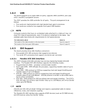
... up to 33 MB/sec. • ATA-66: DMA protocol on IDE bus supporting host and target throttling and transfer rates of the front panel USB headers Refer to Figure 8, page 41 Figure 9, page 42 1.6.3 IDE Support The board provides three IDE interface connectors: • One parallel ATA IDE ... transfer rates of up to 16 MB/sec. • Ultra DMA: DMA protocol on IDE bus allows host and target throttling. Intel Desktop Board D945GCLF2 Technical Product Specification 1.6.2 USB The board supports up to 88 MB/sec. The ICH7's ATA-100 logic can achieve read transfer rates up to 100 MB...
... up to 33 MB/sec. • ATA-66: DMA protocol on IDE bus supporting host and target throttling and transfer rates of the front panel USB headers Refer to Figure 8, page 41 Figure 9, page 42 1.6.3 IDE Support The board provides three IDE interface connectors: • One parallel ATA IDE ... transfer rates of up to 16 MB/sec. • Ultra DMA: DMA protocol on IDE bus allows host and target throttling. Intel Desktop Board D945GCLF2 Technical Product Specification 1.6.2 USB The board supports up to 88 MB/sec. The ICH7's ATA-100 logic can achieve read transfer rates up to 100 MB...

Product Specification
Page 28
...G0 - sleeping state) Sleep (ACPI G1 - Soft off (ACPI G2/G5 - working state) More than four seconds On (ACPI G0 - Intel Desktop Board D945GCLF2 Technical Product Specification 1.13 Power Management Power management is pressed for Off (ACPI G2/G5 - Soft off (ACPI G2/G5 -...8226; Hardware support: ⎯ Power connector ⎯ Fan headers ⎯ LAN wake capabilities ⎯ Instantly Available PC technology ⎯ Wake from USB ⎯ Wake from PS/2 devices ⎯ Power Management Event signal (PME#) wake-up support 1.13.1 ACPI ACPI gives the operating system direct ...
...G0 - sleeping state) Sleep (ACPI G1 - Soft off (ACPI G2/G5 - working state) More than four seconds On (ACPI G0 - Intel Desktop Board D945GCLF2 Technical Product Specification 1.13 Power Management Power management is pressed for Off (ACPI G2/G5 - Soft off (ACPI G2/G5 -...8226; Hardware support: ⎯ Power connector ⎯ Fan headers ⎯ LAN wake capabilities ⎯ Instantly Available PC technology ⎯ Wake from USB ⎯ Wake from PS/2 devices ⎯ Power Management Event signal (PME#) wake-up support 1.13.1 ACPI ACPI gives the operating system direct ...
Product Specification
Page 30
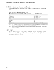
LAN PME# signal Power switch RTC alarm Serial port USB ...from this option to Power On will wake the computer. NOTE The use of these wake-up events from an ACPI state requires an operating ... must fully support ACPI wake events. 30 Wake-up Devices and Events These devices/events can wake the computer from LAN in the S5 state. Intel Desktop Board D945GCLF2 Technical Product Specification 1.13.1.2 Wake-up Devices and Events Table 8 lists the devices or specific events that provides full ACPI support. Note...
LAN PME# signal Power switch RTC alarm Serial port USB ...from this option to Power On will wake the computer. NOTE The use of these wake-up events from an ACPI state requires an operating ... must fully support ACPI wake events. 30 Wake-up Devices and Events These devices/events can wake the computer from LAN in the S5 state. Intel Desktop Board D945GCLF2 Technical Product Specification 1.13.1.2 Wake-up Devices and Events Table 8 lists the devices or specific events that provides full ACPI support. Note...
Product Specification
Page 31
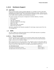
... When an ACPI-enabled system receives the correct command, the power supply removes all non-standby voltages. NOTE The use of Wake from USB technologies from the +5 V standby line. Product Description 1.13.2 Hardware Support CAUTION Ensure that provides full ACPI support. 1.13.2.1 Power ..., including: • Power connector • Fan headers • LAN wake capabilities • Instantly Available PC technology • Wake from USB • PME# signal wake-up support • Wake from PS/2 devices LAN wake capabilities and Instantly Available PC technology require power from ...
... When an ACPI-enabled system receives the correct command, the power supply removes all non-standby voltages. NOTE The use of Wake from USB technologies from the +5 V standby line. Product Description 1.13.2 Hardware Support CAUTION Ensure that provides full ACPI support. 1.13.2.1 Power ..., including: • Power connector • Fan headers • LAN wake capabilities • Instantly Available PC technology • Wake from USB • PME# signal wake-up support • Wake from PS/2 devices LAN wake capabilities and Instantly Available PC technology require power from ...
Product Specification
Page 34
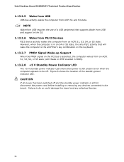
...standby power indicator LED. CAUTION If AC power has been switched off . Failure to the board. Figure 6 shows the location of a USB peripheral that supports Wake from USB and support in BIOS). 1.13.2.8 +5 V Standby Power Indicator LED The +5 V standby power indicator LED shows that will wake the computer... enabled in the OS. 1.13.2.6 Wake from PS/2 Devices PS/2 device activity wakes the computer from ACPI S1 and S3 state. Intel Desktop Board D945GCLF2 Technical Product Specification 1.13.2.5 Wake from USB USB bus activity wakes the computer from an ACPI S1, S3, S4, or S5 state.
...standby power indicator LED. CAUTION If AC power has been switched off . Failure to the board. Figure 6 shows the location of a USB peripheral that supports Wake from USB and support in BIOS). 1.13.2.8 +5 V Standby Power Indicator LED The +5 V standby power indicator LED shows that will wake the computer... enabled in the OS. 1.13.2.6 Wake from PS/2 Devices PS/2 device activity wakes the computer from ACPI S1 and S3 state. Intel Desktop Board D945GCLF2 Technical Product Specification 1.13.2.5 Wake from USB USB bus activity wakes the computer from an ACPI S1, S3, S4, or S5 state.
Product Specification
Page 40
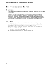
... 40 NOTE Computer systems that meets the requirements for full-speed devices. Intel Desktop Board D945GCLF2 Technical Product Specification 2.2 Connectors and Headers CAUTION Only the following connectors have an unshielded cable attached to a USB port may not meet FCC Class B requirements, even if no device .../headers to power devices external to the computer's chassis. Use shielded cable that have overcurrent protection: Back panel and front panel USB and PS/2. The other internal connectors/headers are not overcurrent protected and should connect only to the computer, the power cable, ...
... 40 NOTE Computer systems that meets the requirements for full-speed devices. Intel Desktop Board D945GCLF2 Technical Product Specification 2.2 Connectors and Headers CAUTION Only the following connectors have an unshielded cable attached to a USB port may not meet FCC Class B requirements, even if no device .../headers to power devices external to the computer's chassis. Use shielded cable that have overcurrent protection: Back panel and front panel USB and PS/2. The other internal connectors/headers are not overcurrent protected and should connect only to the computer, the power cable, ...
Product Specification
Page 41
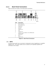
2.2.1 Back Panel Connectors Figure 8 shows the location of the back panel connectors. Back Panel Connectors NOTE The back panel audio line out connector is designed to this output. 41 Poor audio quality occurs if passive (non-amplified) speakers are connected to power headphones or amplified speakers only. Technical Reference Item A B C D E F G H I J K L Description PS/2 mouse port PS/2 keyboard port Parallel port Serial port VGA port USB ports [2] LAN USB ports [2] S-Video out (not available on the D945GCLF2D desktop board) Audio line in Mic in Audio line out Figure 8.
2.2.1 Back Panel Connectors Figure 8 shows the location of the back panel connectors. Back Panel Connectors NOTE The back panel audio line out connector is designed to this output. 41 Poor audio quality occurs if passive (non-amplified) speakers are connected to power headphones or amplified speakers only. Technical Reference Item A B C D E F G H I J K L Description PS/2 mouse port PS/2 keyboard port Parallel port Serial port VGA port USB ports [2] LAN USB ports [2] S-Video out (not available on the D945GCLF2D desktop board) Audio line in Mic in Audio line out Figure 8.
Product Specification
Page 43
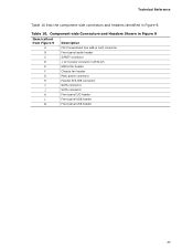
Technical Reference Table 10 lists the component-side connectors and headers identified in card connector B Front panel audio header C S/PDIF connector D +12 V power connector (ATX12V) E GMCH fan header F Chassis fan header G Main power connector H Parallel ATA IDE connector I SATA connector J SATA connector K Front panel I/O header L Front panel USB header M Front panel USB header 43 Component-side Connectors and Headers Shown in Figure 9 Item/callout from Figure 9 Description A PCI Conventional bus add-in Figure 9. Table 10.
Technical Reference Table 10 lists the component-side connectors and headers identified in card connector B Front panel audio header C S/PDIF connector D +12 V power connector (ATX12V) E GMCH fan header F Chassis fan header G Main power connector H Parallel ATA IDE connector I SATA connector J SATA connector K Front panel I/O header L Front panel USB header M Front panel USB header 43 Component-side Connectors and Headers Shown in Figure 9 Item/callout from Figure 9 Description A PCI Conventional bus add-in Figure 9. Table 10.
Product Specification
Page 48
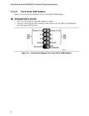
Figure 11. Connection Diagram for high-speed USB devices. Intel Desktop Board D945GCLF2 Technical Product Specification 2.2.2.5 Front Panel USB Headers Figure 11 is a connection diagram for the front panel USB headers. # INTEGRATOR'S NOTES • The +5 V DC power on the USB headers is fused. • Use only a front panel USB connector that conforms to the USB 2.0 specification for Front Panel USB Headers 48
Figure 11. Connection Diagram for high-speed USB devices. Intel Desktop Board D945GCLF2 Technical Product Specification 2.2.2.5 Front Panel USB Headers Figure 11 is a connection diagram for the front panel USB headers. # INTEGRATOR'S NOTES • The +5 V DC power on the USB headers is fused. • Use only a front panel USB connector that conforms to the USB 2.0 specification for Front Panel USB Headers 48
Product Specification
Page 58
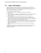
... in the BIOS Setup program is set to Enabled and follow the operating system's installation instructions. 58 Additional USB legacy feature options can be used to configure the operating system. (Keyboards and mice are recognized by the BIOS...Legacy USB support is set to Enabled. Legacy USB support operates as follows: 1. POST completes. 5. POST begins. 3. Legacy USB support is enabled by the operating system, and Legacy USB support from the BIOS is disabled. 2. Intel Desktop Board D945GCLF2 Technical Product Specification 3.5 Legacy USB Support Legacy USB support enables USB ...
... in the BIOS Setup program is set to Enabled and follow the operating system's installation instructions. 58 Additional USB legacy feature options can be used to configure the operating system. (Keyboards and mice are recognized by the BIOS...Legacy USB support is set to Enabled. Legacy USB support operates as follows: 1. POST completes. 5. POST begins. 3. Legacy USB support is enabled by the operating system, and Legacy USB support from the BIOS is disabled. 2. Intel Desktop Board D945GCLF2 Technical Product Specification 3.5 Legacy USB Support Legacy USB support enables USB ...
Product Specification
Page 59
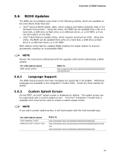
...the instructions distributed with the Intel branded logo. Using this utility, the BIOS can be updated from a file on a hard disk, a USB drive (a flash drive or a USB hard drive), or a CD-ROM, or from the file location on the Intel World Wide Web site: • Intel® Express BIOS Update ...utility, which requires booting from Intel can be updated using either of BIOS Features 3.6 BIOS...
...the instructions distributed with the Intel branded logo. Using this utility, the BIOS can be updated from a file on a hard disk, a USB drive (a flash drive or a USB hard drive), or a CD-ROM, or from the file location on the Intel World Wide Web site: • Intel® Express BIOS Update ...utility, which requires booting from Intel can be updated using either of BIOS Features 3.6 BIOS...
Product Specification
Page 60
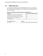
...Recovery Media Type Can be used for BIOS recovery. however, if an interruption occurs, the BIOS could be made bootable. Table 28. Intel Desktop Board D945GCLF2 Technical Product Specification 3.7 BIOS Recovery It is unlikely that can and cannot be used for BIOS recovery? CD-ROM ... connected to the Parallel ATA interface Yes CD-ROM drive connected to the Serial ATA interface Yes USB removable drive (a USB Flash Drive, for example) Yes USB diskette drive (with a 1.44 MB diskette) No USB hard disk drive No For information about BIOS recovery Refer to be damaged.
...Recovery Media Type Can be used for BIOS recovery. however, if an interruption occurs, the BIOS could be made bootable. Table 28. Intel Desktop Board D945GCLF2 Technical Product Specification 3.7 BIOS Recovery It is unlikely that can and cannot be used for BIOS recovery? CD-ROM ... connected to the Parallel ATA interface Yes CD-ROM drive connected to the Serial ATA interface Yes USB removable drive (a USB Flash Drive, for example) Yes USB diskette drive (with a 1.44 MB diskette) No USB hard disk drive No For information about BIOS recovery Refer to be damaged.
Product Specification
Page 61
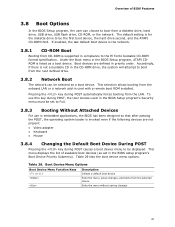
... • Keyboard • Mouse 3.8.4 Changing the Default Boot Device During POST Pressing the key during POST automatically forces booting from a diskette drive, hard drive, USB drive, USB flash drive, CD-ROM, or the network. This menu displays the list of BIOS Features 3.8 Boot Options In the BIOS Setup program, the user can...
... • Keyboard • Mouse 3.8.4 Changing the Default Boot Device During POST Pressing the key during POST automatically forces booting from a diskette drive, hard drive, USB drive, USB flash drive, CD-ROM, or the network. This menu displays the list of BIOS Features 3.8 Boot Options In the BIOS Setup program, the user can...
Product Specification
Page 67
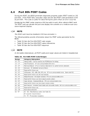
... 34. A0 - Error Messages and Beep Codes 4.4 Port 80h POST Codes During the POST, the BIOS generates diagnostic progress codes (POST codes) to I /O Busses: PCI, USB, ISA, ATA, etc. 5F is no memory detected or no useful memory detected. 30 - 3F 40 - 4F Recovery: 3F indicated recovery failure. C0 - EF: boot...
... 34. A0 - Error Messages and Beep Codes 4.4 Port 80h POST Codes During the POST, the BIOS generates diagnostic progress codes (POST codes) to I /O Busses: PCI, USB, ISA, ATA, etc. 5F is no memory detected or no useful memory detected. 30 - 3F 40 - 4F Recovery: 3F indicated recovery failure. C0 - EF: boot...
Product Specification
Page 68
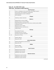
... 50 Enumerating PCI busses 51 Allocating resources to PCI bus 52 Hot Plug PCI controller initialization 53 - 57 Reserved for PCI Bus USB 58 Resetting USB bus 59 Reserved for USB ATA/ATAPI/SATA 5A Resetting PATA/SATA bus and all devices 5B Reserved for ATA SMBus 5C Resetting SMBus 5D Reserved for... controller 72 Enabling the VGA controller Remote Console 78 Resetting the console controller 79 Disabling the console controller 7A Enabling the console controller continued 68 Intel Desktop Board D945GCLF2 Technical Product Specification Table 35.
... 50 Enumerating PCI busses 51 Allocating resources to PCI bus 52 Hot Plug PCI controller initialization 53 - 57 Reserved for PCI Bus USB 58 Resetting USB bus 59 Reserved for USB ATA/ATAPI/SATA 5A Resetting PATA/SATA bus and all devices 5B Reserved for ATA SMBus 5C Resetting SMBus 5D Reserved for... controller 72 Enabling the VGA controller Remote Console 78 Resetting the console controller 79 Disabling the console controller 7A Enabling the console controller continued 68 Intel Desktop Board D945GCLF2 Technical Product Specification Table 35.

