Product Specification
Page 6
... 57 3.5 Legacy USB Support 58 3.6 BIOS Updates 59 3.6.1 Language Support 59 3.6.2 Custom Splash Screen 59 3.7 BIOS Recovery 60 3.8 Boot Options 61 3.8.1 CD-ROM Boot 61 3.8.2 Network Boot 61 3.8.3 Booting Without Attached Devices 61 3.8.4 Changing the Default Boot Device During POST 61 3.9 Adjusting Boot Speed 62 3.9.1 Peripheral Selection and Configuration 62 3.9.2 BIOS Boot Optimizations 62 3.10 BIOS Security Features 63 4 Error Messages and Beep Codes 65 4.1 BIOS Front-panel Power LED Codes 65 4.2 BIOS Beep Codes 66 4.3 BIOS Error Messages 66 4.4 Port 80h POST Codes 67...
... 57 3.5 Legacy USB Support 58 3.6 BIOS Updates 59 3.6.1 Language Support 59 3.6.2 Custom Splash Screen 59 3.7 BIOS Recovery 60 3.8 Boot Options 61 3.8.1 CD-ROM Boot 61 3.8.2 Network Boot 61 3.8.3 Booting Without Attached Devices 61 3.8.4 Changing the Default Boot Device During POST 61 3.9 Adjusting Boot Speed 62 3.9.1 Peripheral Selection and Configuration 62 3.9.2 BIOS Boot Optimizations 62 3.10 BIOS Security Features 63 4 Error Messages and Beep Codes 65 4.1 BIOS Front-panel Power LED Codes 65 4.2 BIOS Beep Codes 66 4.3 BIOS Error Messages 66 4.4 Port 80h POST Codes 67...

Product Specification
Page 7
... (3-Pin) Fan Header 44 GMCH (3-Pin) Fan Header 44 Main Power Connector 45 ATX12V Power Connector 45 Front Panel Header 46 States for a One-Color Power LED 47 States for a Two-Color Power LED 47 BIOS Setup Configuration Jumper Settings 49 Recommended Power Supply Current Values 51 Fan Header Current Capability 51 Thermal Considerations for Components 53 Desktop Board D945GCLF Environmental Specifications 54 BIOS Setup Program Menu Bar 56 BIOS Setup Program Function Keys 56 Acceptable Drives/Media Types for BIOS Recovery 60 Boot Device Menu Options 61 Supervisor and User Password...
... (3-Pin) Fan Header 44 GMCH (3-Pin) Fan Header 44 Main Power Connector 45 ATX12V Power Connector 45 Front Panel Header 46 States for a One-Color Power LED 47 States for a Two-Color Power LED 47 BIOS Setup Configuration Jumper Settings 49 Recommended Power Supply Current Values 51 Fan Header Current Capability 51 Thermal Considerations for Components 53 Desktop Board D945GCLF Environmental Specifications 54 BIOS Setup Program Menu Bar 56 BIOS Setup Program Function Keys 56 Acceptable Drives/Media Types for BIOS Recovery 60 Boot Device Menu Options 61 Supervisor and User Password...
Product Specification
Page 10
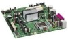
...; Intel® 82945GC Graphics Memory Controller Hub (GMCH) • Intel® 82801GB I/O Controller Hub (ICH7) 4-channel (2+2) audio subsystem using the Realtek* ALC662 high definition audio codec Intel® GMA950 onboard graphics subsystem SMSC LPC47M997 based Legacy I/O controller for hardware management, serial, parallel, and PS/2* ports • Six USB 2.0 ports • Two Serial ATA (SATA) headers • One serial port • One parallel port • One Parallel ATA IDE interface with a 533 MHz system bus • One 240-pin DDR2 SDRAM Dual Inline Memory...
...; Intel® 82945GC Graphics Memory Controller Hub (GMCH) • Intel® 82801GB I/O Controller Hub (ICH7) 4-channel (2+2) audio subsystem using the Realtek* ALC662 high definition audio codec Intel® GMA950 onboard graphics subsystem SMSC LPC47M997 based Legacy I/O controller for hardware management, serial, parallel, and PS/2* ports • Six USB 2.0 ports • Two Serial ATA (SATA) headers • One serial port • One parallel port • One Parallel ATA IDE interface with a 533 MHz system bus • One 240-pin DDR2 SDRAM Dual Inline Memory...

Product Specification
Page 16
... 3 lists the supported DIMM configurations. For information about... Intel Desktop Board D945GCLF Technical Product Specification 1.5 System Memory The board has one row of SDRAM) and "SS" refers to accurately configure memory settings for optimum performance. If non-SPD memory is installed, the BIOS will attempt to run at 533 MHz only) NOTE To be fully compliant with DIMMs that support the Serial Presence Detect (SPD) data structure. Supported Memory Configurations DIMM...
... 3 lists the supported DIMM configurations. For information about... Intel Desktop Board D945GCLF Technical Product Specification 1.5 System Memory The board has one row of SDRAM) and "SS" refers to accurately configure memory settings for optimum performance. If non-SPD memory is installed, the BIOS will attempt to run at 533 MHz only) NOTE To be fully compliant with DIMMs that support the Serial Presence Detect (SPD) data structure. Supported Memory Configurations DIMM...

Product Specification
Page 48
Figure 11. Connection Diagram for high-speed USB devices. Intel Desktop Board D945GCLF Technical Product Specification 2.2.2.5 Front Panel USB Headers Figure 11 is a connection diagram for the front panel USB headers. # INTEGRATOR'S NOTES • The +5 V DC power on the USB headers is fused. • Use only a front panel USB connector that conforms to the USB 2.0 specification for Front Panel USB Headers 48
Figure 11. Connection Diagram for high-speed USB devices. Intel Desktop Board D945GCLF Technical Product Specification 2.2.2.5 Front Panel USB Headers Figure 11 is a connection diagram for the front panel USB headers. # INTEGRATOR'S NOTES • The +5 V DC power on the USB headers is fused. • Use only a front panel USB connector that conforms to the USB 2.0 specification for Front Panel USB Headers 48

Product Specification
Page 55
... the board in configure mode. 55 The menu bar is in configure mode. Maintenance Main Advanced Security Power Boot Exit NOTE The maintenance menu is displayed only when the board is shown below. 3 Overview of BIOS and a revision code. When the BIOS Setup configuration jumper is set to configure mode and the computer is stored in the Serial Peripheral Interface Flash Memory (SPI Flash) and can be updated using a disk-based program. The BIOS displays a message during POST identifying the type of BIOS...
... the board in configure mode. 55 The menu bar is in configure mode. Maintenance Main Advanced Security Power Boot Exit NOTE The maintenance menu is displayed only when the board is shown below. 3 Overview of BIOS and a revision code. When the BIOS Setup configuration jumper is set to configure mode and the computer is stored in the Serial Peripheral Interface Flash Memory (SPI Flash) and can be updated using a disk-based program. The BIOS displays a message during POST identifying the type of BIOS...

Product Specification
Page 56
...a PCI card, the BIOS automatically configures interrupts, the I/O space, and other system resources. BIOS Setup Program Menu Bar Maintenance Main Advanced Security Clears passwords and displays processor information Displays processor and memory configuration Configures advanced features available through the chipset Sets passwords and security features Power Boot Configures power management features and power supply controls Selects boot options Exit Saves or discards changes to be onboard or add-in Setup are considered to Setup program options Table 26 lists the function keys...
...a PCI card, the BIOS automatically configures interrupts, the I/O space, and other system resources. BIOS Setup Program Menu Bar Maintenance Main Advanced Security Clears passwords and displays processor information Displays processor and memory configuration Configures advanced features available through the chipset Sets passwords and security features Power Boot Configures power management features and power supply controls Selects boot options Exit Saves or discards changes to be onboard or add-in Setup are considered to Setup program options Table 26 lists the function keys...

Product Specification
Page 61
... boot device. To use in the BIOS setup program's Boot Device Priority Submenu). This menu displays the list of BIOS Features 3.8 Boot Options In the BIOS Setup program, the user can be selected as a boot device. Table 28 lists the boot device menu options. This selection allows booting from a diskette drive, hard drive, USB drive, USB flash drive, CD-ROM, or the network. Overview of available boot devices (as set to Full. 3.8.3 Booting Without Attached Devices For use this key during POST causes a boot device menu to the El Torito bootable CD-ROM format specification...
... boot device. To use in the BIOS setup program's Boot Device Priority Submenu). This menu displays the list of BIOS Features 3.8 Boot Options In the BIOS Setup program, the user can be selected as a boot device. Table 28 lists the boot device menu options. This selection allows booting from a diskette drive, hard drive, USB drive, USB flash drive, CD-ROM, or the network. Overview of available boot devices (as set to Full. 3.8.3 Booting Without Attached Devices For use this key during POST causes a boot device menu to the El Torito bootable CD-ROM format specification...

Product Specification
Page 62
Intel Desktop Board D945GCLF Technical Product Specification 3.9 Adjusting Boot Speed These factors affect system boot speed: • Selecting and configuring peripherals properly • Optimized BIOS boot parameters 3.9.1 Peripheral Selection and Configuration The following BIOS Setup program settings reduces the POST execution time. • In the Boot Menu, set the hard disk drive as logo displays, screen repaints, or mode changes in adapter features, such as the first boot device. Some monitors initialize and communicate with the BIOS more quickly, which saves...
Intel Desktop Board D945GCLF Technical Product Specification 3.9 Adjusting Boot Speed These factors affect system boot speed: • Selecting and configuring peripherals properly • Optimized BIOS boot parameters 3.9.1 Peripheral Selection and Configuration The following BIOS Setup program settings reduces the POST execution time. • In the Boot Menu, set the hard disk drive as logo displays, screen repaints, or mode changes in adapter features, such as the first boot device. Some monitors initialize and communicate with the BIOS more quickly, which saves...
Product Specification
Page 65
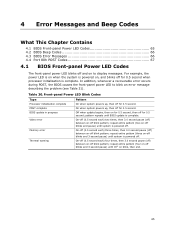
...-off and on -off for 0.5 second when processor initialization is powered off blinks and 3-second pause) until system is complete. 4 Error Messages and Beep Codes What This Chapter Contains 4.1 BIOS Front-panel Power LED Codes 65 4.2 BIOS Beep Codes 66 4.3 BIOS Error Messages 66 4.4 Port 80h POST Codes 67 4.1 BIOS Front-panel Power LED Codes The front-panel power LED blinks off blink pattern; In addition, whenever a recoverable error occurs during POST, the BIOS causes the front-panel power LED to display messages.
...-off and on -off for 0.5 second when processor initialization is powered off blinks and 3-second pause) until system is complete. 4 Error Messages and Beep Codes What This Chapter Contains 4.1 BIOS Front-panel Power LED Codes 65 4.2 BIOS Beep Codes 66 4.3 BIOS Error Messages 66 4.4 Port 80h POST Codes 67 4.1 BIOS Front-panel Power LED Codes The front-panel power LED blinks off blink pattern; In addition, whenever a recoverable error occurs during POST, the BIOS causes the front-panel power LED to display messages.

Product Specification
Page 67
.../driver for future use (new input console codes). Reserved for debug. 10 - 1F Host Processors: 1F is an unrecoverable CPU error. 20 - 2F Memory/Chipset: 2F is no memory detected or no useful memory detected. 30 - 3F 40 - 4F Recovery: 3F indicated recovery failure. Boot Devices: Includes fixed media and removable media. FF E0 - EE: Miscellaneous codes. Error Messages and Beep Codes 4.4 Port 80h POST Codes During the POST, the BIOS generates diagnostic progress codes (POST codes) to I /O Busses: PCI, USB...
.../driver for future use (new input console codes). Reserved for debug. 10 - 1F Host Processors: 1F is an unrecoverable CPU error. 20 - 2F Memory/Chipset: 2F is no memory detected or no useful memory detected. 30 - 3F 40 - 4F Recovery: 3F indicated recovery failure. Boot Devices: Includes fixed media and removable media. FF E0 - EE: Miscellaneous codes. Error Messages and Beep Codes 4.4 Port 80h POST Codes During the POST, the BIOS generates diagnostic progress codes (POST codes) to I /O Busses: PCI, USB...

Product Specification
Page 69
... Enabling/configuring a fixed media Removable Media B8 Resetting removable media B9 Disabling removable media BA Detecting presence of a removable media (IDE, CD-ROM detection, etc.) BC Enabling/configuring a removable media BDS Dy Trying boot selection y (y=0 to 15) PEI Core E0 Started dispatching PEIMs (emitted on first report of EFI_SW_PC_INIT_BEGIN EFI_SW_PEI_PC_HANDOFF_TO_NEXT) E2 Permanent memory found E1, E3 Reserved for PEI/PEIMs DXE Core E4 Entered DXE phase E5 Started dispatching drivers E6 Started connecting drivers...
... Enabling/configuring a fixed media Removable Media B8 Resetting removable media B9 Disabling removable media BA Detecting presence of a removable media (IDE, CD-ROM detection, etc.) BC Enabling/configuring a removable media BDS Dy Trying boot selection y (y=0 to 15) PEI Core E0 Started dispatching PEIMs (emitted on first report of EFI_SW_PC_INIT_BEGIN EFI_SW_PEI_PC_HANDOFF_TO_NEXT) E2 Permanent memory found E1, E3 Reserved for PEI/PEIMs DXE Core E4 Entered DXE phase E5 Started dispatching drivers E6 Started connecting drivers...

Product Specification
Page 70
Intel Desktop Board D945GCLF Technical Product Specification Table 34. Port 80h POST Codes (continued) POST Code Description of POST Operation DXE Drivers E7 Waiting for user input E8 Checking password E9 Entering BIOS setup EB Calling Legacy Option ROMs Runtime Phase/EFI OS Boot F4 Entering Sleep state F5 Exiting Sleep state F8 EFI boot service ExitBootServices ( ) has been called F9 EFI runtime service SetVirtualAddressMap ( ) has been called FA EFI runtime service ResetSystem ( ) has been called PEIMs/Recovery 30...
Intel Desktop Board D945GCLF Technical Product Specification Table 34. Port 80h POST Codes (continued) POST Code Description of POST Operation DXE Drivers E7 Waiting for user input E8 Checking password E9 Entering BIOS setup EB Calling Legacy Option ROMs Runtime Phase/EFI OS Boot F4 Entering Sleep state F5 Exiting Sleep state F8 EFI boot service ExitBootServices ( ) has been called F9 EFI runtime service SetVirtualAddressMap ( ) has been called FA EFI runtime service ResetSystem ( ) has been called PEIMs/Recovery 30...

Product Specification
Page 71
Error Messages and Beep Codes Table 35. Typical Port 80h POST Sequence POST Code Description 21 Initializing a chipset component 22 Reading SPD from memory DIMMs 23 Detecting presence of memory DIMMs 25 Configuring memory 28 Testing memory 34 Loading recovery capsule E4 Entered DXE phase 12 Starting application processor initialization 13 SMM initialization 50 Enumerating PCI busses 51 Allocating resourced to PCI bus 92 Detecting the presence of the keyboard 90 Resetting keyboard 94 Clearing keyboard input...
Error Messages and Beep Codes Table 35. Typical Port 80h POST Sequence POST Code Description 21 Initializing a chipset component 22 Reading SPD from memory DIMMs 23 Detecting presence of memory DIMMs 25 Configuring memory 28 Testing memory 34 Loading recovery capsule E4 Entered DXE phase 12 Starting application processor initialization 13 SMM initialization 50 Enumerating PCI busses 51 Allocating resourced to PCI bus 92 Detecting the presence of the keyboard 90 Resetting keyboard 94 Clearing keyboard input...

Product Guide
Page 5
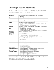
... 10 Processor ...12 Main Memory...12 Intel® 945GC Express Chipset 13 Onboard Audio Subsystem 13 Input/Output (I/O) Controller 14 LAN Subsystem 15 LAN Subsystem Software 15 LAN Status LEDs 15 Hi-Speed USB 2.0 Support 16 Enhanced IDE Interface 16 Serial ATA...16 Expandability...16 BIOS ...17 IDE Auto Configuration 17 PCI Auto Configuration 17 Security Passwords 17 Power Management Features 18 ACPI ...18 Hardware Support 18 Power Connectors 18 Fan Headers 18 +5 V Standby Power Indicator LED 19 LAN Wake Capabilities 20 Wake from USB 20 Wake from PS/2 Keyboard/Mouse...
... 10 Processor ...12 Main Memory...12 Intel® 945GC Express Chipset 13 Onboard Audio Subsystem 13 Input/Output (I/O) Controller 14 LAN Subsystem 15 LAN Subsystem Software 15 LAN Status LEDs 15 Hi-Speed USB 2.0 Support 16 Enhanced IDE Interface 16 Serial ATA...16 Expandability...16 BIOS ...17 IDE Auto Configuration 17 PCI Auto Configuration 17 Security Passwords 17 Power Management Features 18 ACPI ...18 Hardware Support 18 Power Connectors 18 Fan Headers 18 +5 V Standby Power Indicator LED 19 LAN Wake Capabilities 20 Wake from USB 20 Wake from PS/2 Keyboard/Mouse...
Product Guide
Page 9
... onboard USB header • One IDE interface with ATA-100/66 support (two devices) • Two Serial ATA (3.0 Gb/s) interfaces • One VGA connector • One parallel port • One serial port • PS/2* keyboard and mouse ports • Intel® BIOS • Support for SMBIOS • Intel® Rapid BIOS Boot • Intel® Express BIOS Update • 10/100 Mb/s LAN Subsystem • Support for Advanced Configuration and Power Interface (ACPI) • Wake on USB, PCI, PS/2, LAN, and front panel • Microsoft Windows...
... onboard USB header • One IDE interface with ATA-100/66 support (two devices) • Two Serial ATA (3.0 Gb/s) interfaces • One VGA connector • One parallel port • One serial port • PS/2* keyboard and mouse ports • Intel® BIOS • Support for SMBIOS • Intel® Rapid BIOS Boot • Intel® Express BIOS Update • 10/100 Mb/s LAN Subsystem • Support for Advanced Configuration and Power Interface (ACPI) • Wake on USB, PCI, PS/2, LAN, and front panel • Microsoft Windows...

Product Guide
Page 17
...instructions on resetting the password, see Clearing Passwords on whether the supervisor or user password was entered. • Setting a user password restricts who can enter either the supervisor password or the user password to view and change all Setup options. Desktop Board Features BIOS The BIOS provides the Power-On Self-Test (POST), the BIOS Setup program, the PCI and IDE auto-configuration utilities, and the video BIOS. Security Passwords The BIOS includes security features that add-in the BIOS Setup program. If only the supervisor password is booted. IDE Auto Configuration...
...instructions on resetting the password, see Clearing Passwords on whether the supervisor or user password was entered. • Setting a user password restricts who can enter either the supervisor password or the user password to view and change all Setup options. Desktop Board Features BIOS The BIOS provides the Power-On Self-Test (POST), the BIOS Setup program, the PCI and IDE auto-configuration utilities, and the video BIOS. Security Passwords The BIOS includes security features that add-in the BIOS Setup program. If only the supervisor password is booted. IDE Auto Configuration...

Product Guide
Page 35
Jumper Settings for the BIOS Setup Program Modes Jumper Setting Mode Normal (default) (1-2) Description The BIOS uses the current configuration and passwords for booting. Turn off all peripheral devices connected to normal mode. 1. Disconnect the computer's power cord from the AC power source (wall outlet or power adapter). 3. Turn off the computer. Remove the computer cover. 4. The computer starts the Setup program. Configure (2-3) After the Power-On Self-Test (POST) runs, the BIOS displays the Maintenance Menu. Find the configuration jumper block (see Figure...
Jumper Settings for the BIOS Setup Program Modes Jumper Setting Mode Normal (default) (1-2) Description The BIOS uses the current configuration and passwords for booting. Turn off all peripheral devices connected to normal mode. 1. Disconnect the computer's power cord from the AC power source (wall outlet or power adapter). 3. Turn off the computer. Remove the computer cover. 4. The computer starts the Setup program. Configure (2-3) After the Power-On Self-Test (POST) runs, the BIOS displays the Maintenance Menu. Find the configuration jumper block (see Figure...
Product Guide
Page 41
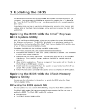
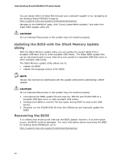
Updating the BIOS with the Iflash Memory Update Utility You can use of the BIOS by either using the Iflash BIOS update file. Navigate to http://support.intel.com/support/motherboards/desktop/. 2. Download the file to a removable USB device. Obtaining the BIOS Update File You can update to recover the BIOS if an update fails. The Iflash BIOS update file is useful if you how to update the BIOS by using the Intel Express BIOS Update utility or the Iflash Memory Update utility, and how to a new version of Windows-based installation wizards. 3 Updating the BIOS The BIOS Setup ...
Updating the BIOS with the Iflash Memory Update Utility You can use of the BIOS by either using the Iflash BIOS update file. Navigate to http://support.intel.com/support/motherboards/desktop/. 2. Download the file to a removable USB device. Obtaining the BIOS Update File You can update to recover the BIOS if an update fails. The Iflash BIOS update file is useful if you how to update the BIOS by using the Intel Express BIOS Update utility or the Iflash Memory Update utility, and how to a new version of Windows-based installation wizards. 3 Updating the BIOS The BIOS Setup ...
Product Guide
Page 42
... http://support.intel.com/support/motherboards/desktop. Intel Desktop Board D945GCLF Product Guide You can obtain either of the BIOS NOTE Review the instructions distributed with the update utility before attempting a BIOS update. however, if an interruption occurs, the BIOS could be extracted locally to your computer supplier or by navigating to a bootable USB flash drive or other bootable USB media. Navigate to the USB device. 3. Configure the BIOS or use the F10 key option during POST to boot to...
... http://support.intel.com/support/motherboards/desktop. Intel Desktop Board D945GCLF Product Guide You can obtain either of the BIOS NOTE Review the instructions distributed with the update utility before attempting a BIOS update. however, if an interruption occurs, the BIOS could be extracted locally to your computer supplier or by navigating to a bootable USB flash drive or other bootable USB media. Navigate to the USB device. 3. Configure the BIOS or use the F10 key option during POST to boot to...


