
Instruction Manual
Page 51
... page 50, carefully cut a hole in position, 17 as shown to the right. 4 5 6 7 3. 8 CONNECTIONS AND INSTALLATION DDMB-132 installation An optional MB-132 flush mount kit is securely mounted in the instrument panel, or wherever you plan to 2 mount the transponder. 3 2. Connect the antenna and power cables, then return the instrument...
... page 50, carefully cut a hole in position, 17 as shown to the right. 4 5 6 7 3. 8 CONNECTIONS AND INSTALLATION DDMB-132 installation An optional MB-132 flush mount kit is securely mounted in the instrument panel, or wherever you plan to 2 mount the transponder. 3 2. Connect the antenna and power cables, then return the instrument...

Instruction Manual
Page 53
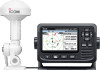
...in 4 700 g, 1.5 lb (including cable and mounting bracket) 10 m, 32.8 ft 5 6 Unit: mm (inch) 7 MA-510TR 8 145 (5.7) 9 110.2 (4.3) 91.3 (3.6) 53.1 (2.1) 10 11 12 166.2 (6.5) 26.2 66.3 (2.3) (1) 13 MA-510TR with the mount bracket 186 (7.3) GPS antenna 26.2 (1) 966.26.(33.(82).3) 14 15 145 (5.7) 16 17 18 164 ...(6.5) 66.2 (2.6) ■■ Options ••MB-132/MB-75 flush mount kit To mount the transponder to a panel....
...in 4 700 g, 1.5 lb (including cable and mounting bracket) 10 m, 32.8 ft 5 6 Unit: mm (inch) 7 MA-510TR 8 145 (5.7) 9 110.2 (4.3) 91.3 (3.6) 53.1 (2.1) 10 11 12 166.2 (6.5) 26.2 66.3 (2.3) (1) 13 MA-510TR with the mount bracket 186 (7.3) GPS antenna 26.2 (1) 966.26.(33.(82).3) 14 15 145 (5.7) 16 17 18 164 ...(6.5) 66.2 (2.6) ■■ Options ••MB-132/MB-75 flush mount kit To mount the transponder to a panel....