Instruction Manual
Page 6
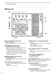
...0.8 V DC y CI-V REMOTE CONTROL JACKS [REMOTE] (pgs. 7-9) Used for band control with an Icom CI-V exciter (transceiver). control level: 5.0 V DC/0.1 A - DO NOT operate the IC-PW1 be used for connecting external equipment such as the EX-627 AUTOMATIC ANTENNA SELECTOR, etc. i CIRCUIT BEAKERS (p....switch. (!0) e REMOTE CONTROLLER CABLE HOLE [CONTROLLER] (p. 10) Used for separation of a non-Icom exciter (transceiver). - Control voltage: -10 to prevent electrical shocks, TVI, BCI and other problems. 3 Ground level: -0.5 to the ALC input jack of the remote controller and linear ampli&#...
...0.8 V DC y CI-V REMOTE CONTROL JACKS [REMOTE] (pgs. 7-9) Used for band control with an Icom CI-V exciter (transceiver). control level: 5.0 V DC/0.1 A - DO NOT operate the IC-PW1 be used for connecting external equipment such as the EX-627 AUTOMATIC ANTENNA SELECTOR, etc. i CIRCUIT BEAKERS (p....switch. (!0) e REMOTE CONTROLLER CABLE HOLE [CONTROLLER] (p. 10) Used for separation of a non-Icom exciter (transceiver). - Control voltage: -10 to prevent electrical shocks, TVI, BCI and other problems. 3 Ground level: -0.5 to the ALC input jack of the remote controller and linear ampli&#...
Instruction Manual
Page 9
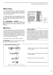
... (TVI), broadcast interference (BCI) and other problems, ground the linear amplifier through the GROUND terminal on and solder it. 30 mm ≈ 9⁄8 in 10 mm ≈ 3⁄8 in 1-2 mm ≈ 1⁄16 in r Screw the coupling ring onto the connector body. 6 The IC-PW1 has an SWR meter to monitor...
... (TVI), broadcast interference (BCI) and other problems, ground the linear amplifier through the GROUND terminal on and solder it. 30 mm ≈ 9⁄8 in 10 mm ≈ 3⁄8 in 1-2 mm ≈ 1⁄16 in r Screw the coupling ring onto the connector body. 6 The IC-PW1 has an SWR meter to monitor...
Instruction Manual
Page 17
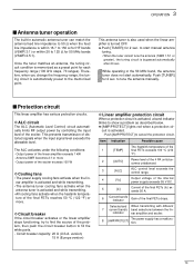
... If the circuit breaker activates or the linear amplifier stops functioning, try to find the source of the problem, then push the circuit breaker button to show a problem as a preset point for 2 sec. Once the tuner matches an antenna, the tuning circuit condition is activated, a band indicator blinks to...
... If the circuit breaker activates or the linear amplifier stops functioning, try to find the source of the problem, then push the circuit breaker button to show a problem as a preset point for 2 sec. Once the tuner matches an antenna, the tuning circuit condition is activated, a band indicator blinks to...
Instruction Manual
Page 18
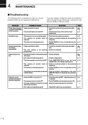
...The indicator lights green.) • The antenna for another band is selected. • The antenna is not adjusted properly. • Check the antenna SWR. PROBLEM POSSIBLE CAUSE Power does not come on the antenna input • Connect properly. REF. and output. • [ALC adj] is not adjusted properly. &#...Set the CI-V address. pgs. 7-9 p. 11 p. 13 p. 13 p. 13 p. 14 Protection circuit activates during short periods of this chart, contact your nearest Icom Dealer or Service Center. p. 11 15 SOLUTION • Check the connection and connection cable pins. • Check for 2 sec.
...The indicator lights green.) • The antenna for another band is selected. • The antenna is not adjusted properly. • Check the antenna SWR. PROBLEM POSSIBLE CAUSE Power does not come on the antenna input • Connect properly. REF. and output. • [ALC adj] is not adjusted properly. &#...Set the CI-V address. pgs. 7-9 p. 11 p. 13 p. 13 p. 13 p. 14 Protection circuit activates during short periods of this chart, contact your nearest Icom Dealer or Service Center. p. 11 15 SOLUTION • Check the connection and connection cable pins. • Check for 2 sec.


