Icom IC-FR9010 Support and Manuals
Get Help and Manuals for this Icom item
View All Support Options Below
Free Icom IC-FR9010 manuals!
Problems with Icom IC-FR9010?
Ask a Question
Free Icom IC-FR9010 manuals!
Problems with Icom IC-FR9010?
Ask a Question
Popular Icom IC-FR9010 Manual Pages
Instruction Manual - Page 1

Operation is subject to the condition that this device does not cause harmful interference. INSTRUCTION MANUAL
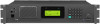
VHF P25 REPEATER
iFR9010
UHF P25 REPEATER
iFR9020
This device complies with Part 15 of the FCC Rules.
Instruction Manual - Page 2

... part or connectors on the repeater rear panel. No risk of at least 6 meters from all persons during transmission. NEVER install
...IC-FR9010/FR9020 VHF/UHF repeaters.
only CAUTION: Changes or modifications to the repeater if left there for this Icom repeater.
NEVER let metal, wire or other ob-
READ THIS INSTRUCTION MANUAL carefully and completely before attempting to firmware...
Instruction Manual - Page 3

... for occupational use with the instruction manual, may also cause you to exceed FCC and IC RF exposure limits. Electromagnetic Interference/Compatibility During transmissions, your expose to RF electromagnetic energy is within this equipment in a residential area is used in accordance with this radio by the manufacturer or antenna specifically authorized by the "General...
Instruction Manual - Page 5

... UPDATE 4 8.7 STATUS REQUEST 4 8.8 PREDEFINED MESSAGES 5 8.9 RADIO MONITOR 5 8.10 SBC LOG 5 9 P25 SQUELCH ADJUSTMENT 5 10 TALKGROUP ALIAS ID 5 11 KEY-LOCK 6 12 MANUAL ...FIRMWARE VERSIONS........ 9 25 DISPLAYING THE SERIAL NUMBER 9
26 DISPLAYING THE PROGRAMMING SOFTWARE VERSION 9
27 DATA CHECK 9 28 ERROR MESSAGES 9 29 FIRMWARE ERROR DETECTION 9 30 RS-232 ERROR DETECTION 10 31 DSP ERROR...
Instruction Manual - Page 6

...function [7] = Indicates Analog channel data [8] = Key lock ON/OFF [9] = No function [A] = Manual CWID send key [B] = Programmed CWID Start/Stop key [C] = Cryptogram Test [D] = No function [Q]...[C] = TX Transmit mode (Clear or Secure), only models with ALM LED)
f. SEMIDUPLEX -
The right 18 letters ...= The LED flashes when an error on .
2 LED DISPLAY
The IC-FR9010/FR9020 has 5 LED's from left ...
Instruction Manual - Page 7

...unit ID on the same NAC.
RX TX
C001 Figure 4
TAC 2
MD N
Light - 15
5 CHANNEL SELECTION
The IC-FR9010/FR9020 has capability of up to scroll through the menu. Push [CH] + [5] + [0] + [0]
6 P25 ... backlight has been turned ON with [SHIFT] + [1] (backlight ON/OFF). Figure 4 shows the Backlight Timer set for ID entry.)
RX TX
C001 GPC 00001
Figure 5 RX TX
TAC 2
MD N
C001
TAC 2
GPC ...
Instruction Manual - Page 8

... N
C001 IDC 12345
Figure 9
TAC 2
MD N
7 P25 PTT MODE
Push [D] to work with any P25 radio under the TIA specifications. When the display shows PTT is pushed. Figure 9 shows completed entry, [1] + [2] + [3] + [4] + [5] + [B]. The IC-FR9010/FR9020 has been developed to select PTT (Push-To-Talk) mode. Reboot the radio to enter the SBC mode...
Instruction Manual - Page 9

..., push [F] then push [A] or [B] until the selection is sent the target unit should respond with the current status. The password must match the password entered in the BTIII program for inhibit to occur.
8.6 STATUS UPDATE
Used to disable a subscriber unit (mobile or portable). Status Request To: 366
USR: 2
UNT: 0
MD N
FM: 00000366
(ACK...
Instruction Manual - Page 11

... to show the TGID. This symbol shows on the pre-setting, this information cannot be enabled in programming to normal operation,... 5) TX CTCSS/DCS, CTCSS and DCS are not locked. CWID sending Code: ICOM
C001
TAC 2
MD N
RX TX
C001
TAC 2
CWID function start...KeyUnlock icon is locked. 11 KEY-LOCK
Push [SHIFT] + [8] to manually send the programmed CWID. If [PTT], [MON] and [SHIFT] needs ...
Instruction Manual - Page 12

... Unit ID (source address) 8. Radio Inhibit RCV
2. TX-NAC
10. Status Update RCV
4. Status Request RCV
5. Short Message RCV
6. Radio Monitor RCV
7.
Push...settings. Figure 33 Indicates the Backlight is selected, the icon " " appears. If the radio is programmed for TX and RX. RX TX
C001
TAC 2
GPC 00001
Figure 34
19 CALLER ID
MD N
In Simplex mode the IC-FR9010...
Instruction Manual - Page 13

...be pushed to the chart on an individual channel.
23 REMOTE CONTROL
IC-FR9010/FR9020 can be controlled remotely by pulling pin 24 of the EXT ...frequency and CTCSS/DCS.
21.2 DIGITAL
Matching NAC (Network Access Code); If the programmed NAC matches the received NAC it transmits... described in RX NAC If the RX NAC is set for Channel control pinouts and other related information. If the...
Instruction Manual - Page 14

... automatically.
9 Figure 39
Figure 40 shows the programmable starting message "Your Message Here". Set by p-kgprg 023195 Figure 42
27 DATA CHECK
The IC-FR9010/FR9020 has a self diagnostic function. 24 DISPLAYING THE FIRMWARE VERSIONS
Both the radio and DSP firmware versions are open or a channel is selected remotely that is indicated. Figure 46 displays...
Instruction Manual - Page 15

... board is installed correctly, and the correct firmware version is a problem with the DSP, the following messages are shown on the display. Receive timeout
31 DSP ERROR DETECTION
When there is displayed at startup. Figure 47 shows DSP failure.
30 RS-232 ERROR DETECTION
If the communications between PC and the repeater have trouble, the following...
Instruction Manual - Page 16

...
Ground
Push to talk
l 0 to +3.3 V DC 0 V = external
mode
O 12 V DC
800 mA Max out
NOTE: Pins 1-4, 6 and 9 are as follows:
Pin No. The functions of IC-FR9010/FR9020. See page 8 for more information on the rear panel of each pin are only available when pin 24 (Remote Mode) is provided on display...
Icom IC-FR9010 Reviews
We have not received any reviews for Icom yet.