Instruction Manual
Page 9
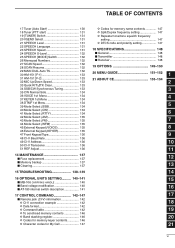
... Keypad Type 136 48 CI-V Baud Rate 136 49 CI-V Address 136 50 CI-V Transceive 136 51 REF Adjust 136 14 MAINTENANCE 137 ■ Fuse replacement 137 ■ Memory backup 137 ■ Cleaning 137 15 TROUBLESHOOTING 138-139 16 OPTIONAL UNITS SETTING 140-141 ■ MB-106 carrying handle 140 ■...
... Keypad Type 136 48 CI-V Baud Rate 136 49 CI-V Address 136 50 CI-V Transceive 136 51 REF Adjust 136 14 MAINTENANCE 137 ■ Fuse replacement 137 ■ Memory backup 137 ■ Cleaning 137 15 TROUBLESHOOTING 138-139 16 OPTIONAL UNITS SETTING 140-141 ■ MB-106 carrying handle 140 ■...
Instruction Manual
Page 146
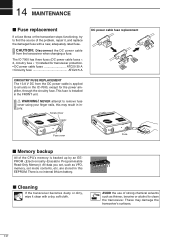
...alcohol to all units in the FRONT unit. The IC-7000 has three fuses (DC power cable fuses × 2, circuitry fuse × 1) installed for the power amplifier, through the circuitry fuse. Screw driver DC power cable fuse replacement Fuse cover ■ Memory backup All of the .... NEVER attempt to find the source of the CPU's memory is installed in the IC-7000, except for transceiver protection. • DC power cable fuses ATC20 30 A • Circuitry fuse ATC20 5 A CIRCUITRY FUSE REPLACEMENT The 13.8 V DC from the transceiver when changing a fuse. All data you ...
...alcohol to all units in the FRONT unit. The IC-7000 has three fuses (DC power cable fuses × 2, circuitry fuse × 1) installed for the power amplifier, through the circuitry fuse. Screw driver DC power cable fuse replacement Fuse cover ■ Memory backup All of the .... NEVER attempt to find the source of the CPU's memory is installed in the IC-7000, except for transceiver protection. • DC power cable fuses ATC20 30 A • Circuitry fuse ATC20 5 A CIRCUITRY FUSE REPLACEMENT The 13.8 V DC from the transceiver when changing a fuse. All data you ...

Instruction Manual
Page 147
... 14 15 RECEIVE 138 Rotate [AF] clockwise to turn the function p. 78 OFF. check the SEND line of this chart, contact your nearest Icom Dealer or Service Center. Sensitivity is activated. The antenna is cut or shorted. The antenna feed line is not connected properly. The antenna is ...you correct problems which are using Check the battery voltage. - phone plug connection. improper conditions. Push [PBT/M-ch/RIT(CLR)] for the cause, then replace the fuse with a spare one. (Fuses are connected. a 12 V battery as the power source. POWER SUPPLY PROBLEM Power does not come on the...
... 14 15 RECEIVE 138 Rotate [AF] clockwise to turn the function p. 78 OFF. check the SEND line of this chart, contact your nearest Icom Dealer or Service Center. Sensitivity is activated. The antenna is cut or shorted. The antenna feed line is not connected properly. The antenna is ...you correct problems which are using Check the battery voltage. - phone plug connection. improper conditions. Push [PBT/M-ch/RIT(CLR)] for the cause, then replace the fuse with a spare one. (Fuses are connected. a 12 V battery as the power source. POWER SUPPLY PROBLEM Power does not come on the...
Service Manual
Page 2
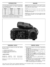
... change without notice or obligation. ALWAYS connect a 50 dB to include the following four points when ordering replacement parts: 1. 10-digit Icom parts number 2. Quantity required 5030002820 LCD LTA025A161A IC-7000 8810009610 Screw FH M2.6 × 6 ZK IC-7000 Front unit 5 pieces Top cover10 pieces Addresses are registered trademarks of the power supply when connecting the...
... change without notice or obligation. ALWAYS connect a 50 dB to include the following four points when ordering replacement parts: 1. 10-digit Icom parts number 2. Quantity required 5030002820 LCD LTA025A161A IC-7000 8810009610 Screw FH M2.6 × 6 ZK IC-7000 Front unit 5 pieces Top cover10 pieces Addresses are registered trademarks of the power supply when connecting the...

Service Manual
Page 30
... (T: Mounted on the Top side, B: Mounted on the Bottom side) S.=Surface mount 5 - 1 UNIT NAME 0324270102 U 7000 #02 FRONT [EUR], [FRA], [ESP], [EXP], [UK] 0324270105 U 7000 #05 FRONT [USA] [FRONT UNIT] REF NO. ORDER NO. DESCRIPTION L1 L2 L3 L51 L53 L101 L151 L152 L251 L252... CR-747 [USA] B [Others] B B 87/43.5 87/43.5 106.5/27 [DISPLAY UNIT] REF NO. SECTION 5 PARTS LIST [REPLACEMENT UNITS] ORDER NO. DESCRIPTION IC1 IC101 IC151 IC301 IC506 IC651 IC2003 IC2007 6910016730 1180001071 1180002201 1110002751 1120003010 1110005420 1140013140 1110005821 S.DCC XC9504B092ARN...
... (T: Mounted on the Top side, B: Mounted on the Bottom side) S.=Surface mount 5 - 1 UNIT NAME 0324270102 U 7000 #02 FRONT [EUR], [FRA], [ESP], [EXP], [UK] 0324270105 U 7000 #05 FRONT [USA] [FRONT UNIT] REF NO. ORDER NO. DESCRIPTION L1 L2 L3 L51 L53 L101 L151 L152 L251 L252... CR-747 [USA] B [Others] B B 87/43.5 87/43.5 106.5/27 [DISPLAY UNIT] REF NO. SECTION 5 PARTS LIST [REPLACEMENT UNITS] ORDER NO. DESCRIPTION IC1 IC101 IC151 IC301 IC506 IC651 IC2003 IC2007 6910016730 1180001071 1180002201 1110002751 1120003010 1110005420 1140013140 1110005821 S.DCC XC9504B092ARN...
