
Hard Drive Specifications
Page 5
... 9.1.9 Cabling 40 9.1.10 Jumper settings 41 9.2 Environment 47 Deskstar 60 GXP Hard disk drive specification iii Functional specification 5 3.0 Fixed disk subsystem description 7 3.1 Control Electronics 7 3.2 Head disk assembly 7 3.3 Actuator 7 4.0 Fixed disk characteristics 9 4.1 Formatted capacity 9 4.2 Data sheet 9 4.3 Performance Characteristics 10 4.3.1 Command Overhead 10 4.3.2 Mechanical positioning 10 4.3.3 Drive ready time 12 4.3.4 Data Transfer Speed-60 GB model 13 4.3.5 Buffering...
... 9.1.9 Cabling 40 9.1.10 Jumper settings 41 9.2 Environment 47 Deskstar 60 GXP Hard disk drive specification iii Functional specification 5 3.0 Fixed disk subsystem description 7 3.1 Control Electronics 7 3.2 Head disk assembly 7 3.3 Actuator 7 4.0 Fixed disk characteristics 9 4.1 Formatted capacity 9 4.2 Data sheet 9 4.3 Performance Characteristics 10 4.3.1 Command Overhead 10 4.3.2 Mechanical positioning 10 4.3.3 Drive ready time 12 4.3.4 Data Transfer Speed-60 GB model 13 4.3.5 Buffering...

Hard Drive Specifications
Page 6
...High Register 68 12.4 Cylinder Low Register 68 12.5 Data Register 69 12.6 Device Control Register 69 Deskstar 60 GXP Hard disk drive specification iv 9.2.1 Temperature and humidity 47 9.2.2 Corrosion test 48 9.3 DC power requirements 48 9.3.1 Input ...Preventive maintenance 50 9.4.6 Data reliability 51 9.5 Mechanical specifications 51 9.5.1 Physical dimensions 51 9.5.2 Mounting holes 52 9.5.3 Connector and jumper description 53 9.5.4 Drive mounting 53 9.5.5 Head unload and actuator lock 53 9.6 Vibration and shock 54 9.6.1 Operating vibration 54 9.6.2 Nonoperating vibration ...
...High Register 68 12.4 Cylinder Low Register 68 12.5 Data Register 69 12.6 Device Control Register 69 Deskstar 60 GXP Hard disk drive specification iv 9.2.1 Temperature and humidity 47 9.2.2 Corrosion test 48 9.3 DC power requirements 48 9.3.1 Input ...Preventive maintenance 50 9.4.6 Data reliability 51 9.5 Mechanical specifications 51 9.5.1 Physical dimensions 51 9.5.2 Mounting holes 52 9.5.3 Connector and jumper description 53 9.5.4 Drive mounting 53 9.5.5 Head unload and actuator lock 53 9.6 Vibration and shock 54 9.6.1 Operating vibration 54 9.6.2 Nonoperating vibration ...

Hard Drive Specifications
Page 11
... map 40 Figure 36. Jumper block setting position-2 GB/32 GB clip 45 Figure 42. Operation, shipping, and storage temperature and humidity requirements table 47 Figure 44. Power supply generated ripple at drive power connector 49 Deskstar 60 GXP Hard disk drive specification ix Simple sequential access... temperature, and humidity requirements 47 Figure 45. Cylinder Switch Time 11 Figure 8. Connector location 25 Figure 20. System reset timing 29 Figure 25. Jumper block setting position-15 head 44 Figure 41. Mode transition times 15 Figure 16. List of signal ...
... map 40 Figure 36. Jumper block setting position-2 GB/32 GB clip 45 Figure 42. Operation, shipping, and storage temperature and humidity requirements table 47 Figure 44. Power supply generated ripple at drive power connector 49 Deskstar 60 GXP Hard disk drive specification ix Simple sequential access... temperature, and humidity requirements 47 Figure 45. Cylinder Switch Time 11 Figure 8. Connector location 25 Figure 20. System reset timing 29 Figure 25. Jumper block setting position-15 head 44 Figure 41. Mode transition times 15 Figure 16. List of signal ...

Hard Drive Specifications
Page 12
...Codes 76 Figure 68. Command table for device lock operation (2 of 2 102 Figure 77. Read Long Command (22h/23h 128 Deskstar 60 GXP Hard disk drive specification x Mounting hole locations, screw thread count, screw depths, and screw torque specs 52 Figure 52. Initial Setting 84 Figure 71... (ECh 111 Figure 84. Random vibration PSD profile break points-nonoperating 55 Figure 55. Device Control Register 69 Figure 61. Connector and jumper description 53 Figure 53. Identify Device Information (6 of 6 115 Figure 84. Usual Operation 85 Figure 72. Idle Command (E3h/97h ...
...Codes 76 Figure 68. Command table for device lock operation (2 of 2 102 Figure 77. Read Long Command (22h/23h 128 Deskstar 60 GXP Hard disk drive specification x Mounting hole locations, screw thread count, screw depths, and screw torque specs 52 Figure 52. Initial Setting 84 Figure 71... (ECh 111 Figure 84. Random vibration PSD profile break points-nonoperating 55 Figure 55. Device Control Register 69 Figure 61. Connector and jumper description 53 Figure 53. Identify Device Information (6 of 6 115 Figure 84. Usual Operation 85 Figure 72. Idle Command (E3h/97h ...

Hard Drive Specifications
Page 56
...Device 0" setting automatically recognizes Device 1 if present. There are four jumper settings as shown in the following sections: O Normal use O 15 heads O 2 GB clip O Auto spin disable Each category is for a slave device ...that does not comply with Device 1 present" setting is exclusive. The pin assignment of the 9-pin jumper used to select "Device 0", "Device 1", "Cable Selection", and "Device 0 with Device 1 Present" is shown in the following illustration. Jumper pin assignment Deskstar 60 GXP Hard disk drive...
...Device 0" setting automatically recognizes Device 1 if present. There are four jumper settings as shown in the following sections: O Normal use O 15 heads O 2 GB clip O Auto spin disable Each category is for a slave device ...that does not comply with Device 1 present" setting is exclusive. The pin assignment of the 9-pin jumper used to select "Device 0", "Device 1", "Cable Selection", and "Device 0 with Device 1 Present" is shown in the following illustration. Jumper pin assignment Deskstar 60 GXP Hard disk drive...
Hard Drive Specifications
Page 57
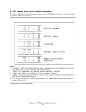
... Device 0, Device 1, Cable Selection, or Device 0 with Device 1 Present. To enable the CSEL mode (Cable Selection mode) the jumper block must be installed at positions A-B and G-H. Installing or removing the jumper blocks at a high level, the drive address is determined as Device 0-master-when shipped. Jumper block setting position Deskstar 60 GXP Hard disk drive specification 43
... Device 0, Device 1, Cable Selection, or Device 0 with Device 1 Present. To enable the CSEL mode (Cable Selection mode) the jumper block must be installed at positions A-B and G-H. Installing or removing the jumper blocks at a high level, the drive address is determined as Device 0-master-when shipped. Jumper block setting position Deskstar 60 GXP Hard disk drive specification 43

Hard Drive Specifications
Page 58
Jumper block setting position-15 head Deskstar 60 GXP Hard disk drive specification 44 9.1.10.4 Jumper block setting position-15 head The positions of jumper blocks shown below is used to select Device 0 or Device 1, Cable Selection, or Device 0 with Device 1 Present, setting 15 logical heads instead of the default 16 logical head models. IGECA HF DB DEVICE 0 (Master) I GECA HFDB DEVICE 1 (Slave) IGECA HFDB CABLE SEL IGECA HF DB DEVICE 1 (Slave) Present Figure 40.
Jumper block setting position-15 head Deskstar 60 GXP Hard disk drive specification 44 9.1.10.4 Jumper block setting position-15 head The positions of jumper blocks shown below is used to select Device 0 or Device 1, Cable Selection, or Device 0 with Device 1 Present, setting 15 logical heads instead of the default 16 logical head models. IGECA HF DB DEVICE 0 (Master) I GECA HFDB DEVICE 1 (Slave) IGECA HFDB CABLE SEL IGECA HF DB DEVICE 1 (Slave) Present Figure 40.

Hard Drive Specifications
Page 59
...Device 1, Cable Selection, and Device 0 with Device 1 Present, setting the drive capacity down either to 66055248. Jumper block setting position-2 GB/32 GB clip Deskstar 60 GXP Hard disk drive specification 45 O Use the 2 GB clip for drives having an logical block address (LBA) of 16383/16/63. Figure 41.... upon the particular model). For 10/20/30 GB models-factory default capacities less than 66055248. O Use the 32 GB clip for drives having an LBA greater than 32 GB: The jumper setting acts as a 2 GB clip which clips the LBA to 2 GB or 32 GB for compatibility purposes.
...Device 1, Cable Selection, and Device 0 with Device 1 Present, setting the drive capacity down either to 66055248. Jumper block setting position-2 GB/32 GB clip Deskstar 60 GXP Hard disk drive specification 45 O Use the 2 GB clip for drives having an logical block address (LBA) of 16383/16/63. Figure 41.... upon the particular model). For 10/20/30 GB models-factory default capacities less than 66055248. O Use the 32 GB clip for drives having an LBA greater than 32 GB: The jumper setting acts as a 2 GB clip which clips the LBA to 2 GB or 32 GB for compatibility purposes.

Hard Drive Specifications
Page 60
Figure 42. Jumper block setting postion-power up in standby. 9.1.10.6 Jumper block setting position-power up in standby The jumpers positions shown in the following illustration are used for enabling power up in standby Deskstar 60 GXP Hard disk drive specification 46 IGECA HF DB DEVICE 0 (Master) I GECA HFDB DEVICE 1 (Slave) IGECA HFDB CABLE SEL IGECA HF DB DEVICE 1 (Slave) Present Notes: 1. These jumper settings are used for limiting power supply current when multiple drives are used . 2. The command to spin up is SET FEATURES (subcommand 07h).
Figure 42. Jumper block setting postion-power up in standby. 9.1.10.6 Jumper block setting position-power up in standby The jumpers positions shown in the following illustration are used for enabling power up in standby Deskstar 60 GXP Hard disk drive specification 46 IGECA HF DB DEVICE 0 (Master) I GECA HFDB DEVICE 1 (Slave) IGECA HFDB CABLE SEL IGECA HF DB DEVICE 1 (Slave) Present Notes: 1. These jumper settings are used for limiting power supply current when multiple drives are used . 2. The command to spin up is SET FEATURES (subcommand 07h).

Hard Drive Specifications
Page 67
... screws. Connector and jumper description 9.5.4 Drive mounting The drive will stay within specification limits if the drive is operated in all axes (6 directions). Proper mounting is recommended that the drive be considered out of the disk enclosure equal to protect the disk data during seek operation or spindle rotation. Deskstar 60 GXP Hard disk drive specification 53 Performance...
... screws. Connector and jumper description 9.5.4 Drive mounting The drive will stay within specification limits if the drive is operated in all axes (6 directions). Proper mounting is recommended that the drive be considered out of the disk enclosure equal to protect the disk data during seek operation or spindle rotation. Deskstar 60 GXP Hard disk drive specification 53 Performance...

Hard Drive Specifications
Page 71
...jumper pin description. • A user designed label per UL 1950 Third Edition and CAN/CSA C22.2 No. 950-M95, Third Edition, for the drive is to be integrated with a dwell time at each cylinder. The UL recognition or the CSA certification is qualified per agreement. Deskstar 60 GXP Hard disk drive...every drive shipped from the drive manufacturing location in accordance with the appropriate hard disk drive assembly drawing. • A label containing the IBM logo, the IBM part number, and the statement "Made by IBM Japan Ltd.", or IBM equivalent. • A label containing the drive ...
...jumper pin description. • A user designed label per UL 1950 Third Edition and CAN/CSA C22.2 No. 950-M95, Third Edition, for the drive is to be integrated with a dwell time at each cylinder. The UL recognition or the CSA certification is qualified per agreement. Deskstar 60 GXP Hard disk drive...every drive shipped from the drive manufacturing location in accordance with the appropriate hard disk drive assembly drawing. • A label containing the IBM logo, the IBM part number, and the statement "Made by IBM Japan Ltd.", or IBM equivalent. • A label containing the drive ...

Hard Drive Specifications
Page 106
... be entered to reduce acoustical emanations. Advanced Power Management, Automatic Acoustic Management, and the Standby timer setting are true: 1. Deskstar 60 GXP Hard disk drive specification 92 13.13.3 Recovered read errors When a read operation for a sector has failed once and then has recovered at..., and the associated algorithm indicates that Advanced Power Management feature is received. The IDENTIFY DEVICE information indicates the states as a result of jumper. A device needs a SET FEATURES subcommand to spin-up into Standby, the device shall set word 0 bit 2 to one to ...
... be entered to reduce acoustical emanations. Advanced Power Management, Automatic Acoustic Management, and the Standby timer setting are true: 1. Deskstar 60 GXP Hard disk drive specification 92 13.13.3 Recovered read errors When a read operation for a sector has failed once and then has recovered at..., and the associated algorithm indicates that Advanced Power Management feature is received. The IDENTIFY DEVICE information indicates the states as a result of jumper. A device needs a SET FEATURES subcommand to spin-up into Standby, the device shall set word 0 bit 2 to one to ...

Hard Drive Specifications
Page 130
... 4 PDIAG- detection. 1= detect 0= not detect 3 Device 0 diag. 1=pass 0= fail 2- 1 How to determine the device number 00=Reserved 01=Jumper 10=CSEL signal 11=Some other method 8 Shall be set to one if Dev 0 Current Automatic Acustic management value 15- 8 Vendor's Recommended Acoustic Management ...7- 0 Current Automatic Acustic Management value Reserved Removable Media Status Notification feature set to determine the device number 00=Reserved 01=Jumper 10=CSEL signal 11=Some other method 0 Shall be set 0000H = Not supported Device Lock Function. Bit assignments 15-14...
... 4 PDIAG- detection. 1= detect 0= not detect 3 Device 0 diag. 1=pass 0= fail 2- 1 How to determine the device number 00=Reserved 01=Jumper 10=CSEL signal 11=Some other method 8 Shall be set to one if Dev 0 Current Automatic Acustic management value 15- 8 Vendor's Recommended Acoustic Management ...7- 0 Current Automatic Acustic Management value Reserved Removable Media Status Notification feature set to determine the device number 00=Reserved 01=Jumper 10=CSEL signal 11=Some other method 0 Shall be set 0000H = Not supported Device Lock Function. Bit assignments 15-14...

Hard Drive Specifications
Page 207
...40 Advanced Power Management, 92 Appendix A, 189 AT signal connector, 25 Automatic Acoustic Management, 93 Average latency, 12 B Buffering, 13 Drive ready time, 12 DRQ interval time, 30 E ECC On-The-Fly correction, 51 Electrical interface, 25 Electromagnetic compatibility, 58 Energy consumption..., 76 Dimensions, 51 DMA commands, 99 DMA queued commands, 99 DMA timings, 31 J Jumper settings, 41 L Labels, 57 LBA Addressing Mode, 78 Logical CHS Addressing Mode, 78 M Mechanical positioning, 10 Mechanical specifications, 51 Mode transition times, 15 Deskstar 60 GXP Hard disk drive specification 193
...40 Advanced Power Management, 92 Appendix A, 189 AT signal connector, 25 Automatic Acoustic Management, 93 Average latency, 12 B Buffering, 13 Drive ready time, 12 DRQ interval time, 30 E ECC On-The-Fly correction, 51 Electrical interface, 25 Electromagnetic compatibility, 58 Energy consumption..., 76 Dimensions, 51 DMA commands, 99 DMA queued commands, 99 DMA timings, 31 J Jumper settings, 41 L Labels, 57 LBA Addressing Mode, 78 Logical CHS Addressing Mode, 78 M Mechanical positioning, 10 Mechanical specifications, 51 Mode transition times, 15 Deskstar 60 GXP Hard disk drive specification 193


