

Parts Manual
Page 15
...48 532 19 73-79 49 873 90 06-00 50 817 49 06-36 52 532 19 31-97 DESCRIPTION Deck Weldment Mower Cover Mandrel LH Cover Mandrel RH Bolt 7/16 Asm. Blade Blade High Lift Rod Anti-Sway Shaft ...Asm. Top Lock Pulley, Idler, 4.50 Hub Arm, Idler Screw, Thdroll. 1/4-20 x 5/8 Belt Deck Drive Pulley Idler 4.50 RAW Nut, Lock Flg. 3/8-16 unc Screw TT 3/8-16 x 2-1/4 Pulley Idler 48" Primary KEY PART NO.... 532 41 64-05 - - 532 18 72-92 - - 532 41 82-23 DESCRIPTION Bolt Carr. YTH24V48 (96045004600), PRODUCT NO. 960 45 00-46 MOWER DECK KEY PART NO. MODEL NO.
...48 532 19 73-79 49 873 90 06-00 50 817 49 06-36 52 532 19 31-97 DESCRIPTION Deck Weldment Mower Cover Mandrel LH Cover Mandrel RH Bolt 7/16 Asm. Blade Blade High Lift Rod Anti-Sway Shaft ...Asm. Top Lock Pulley, Idler, 4.50 Hub Arm, Idler Screw, Thdroll. 1/4-20 x 5/8 Belt Deck Drive Pulley Idler 4.50 RAW Nut, Lock Flg. 3/8-16 unc Screw TT 3/8-16 x 2-1/4 Pulley Idler 48" Primary KEY PART NO.... 532 41 64-05 - - 532 18 72-92 - - 532 41 82-23 DESCRIPTION Bolt Carr. YTH24V48 (96045004600), PRODUCT NO. 960 45 00-46 MOWER DECK KEY PART NO. MODEL NO.

Owner Manual
Page 6
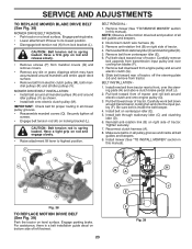
...YOUR TRACTOR, PAY EXTRA ATTENTION TO THE FOLLOWING IMPORTANT ITEMS: ✓ Engine oil is at the factory). ✓ Be sure mower deck is operating properly. Follow proper starting and transmission purging instructions (See "TO START ENGINE" and "PURGE TRANSMISSION" in the Service and Adjustments...-to-rear for shipping purposes. eration System (ROS) are shown for replacing motion and mower blade drive belts in the Operation section of this manual). 6 CHECK DECK LEVELNESS For best cutting results, mower housing should be properly inflated for the first time. Correct tire pressure...
...YOUR TRACTOR, PAY EXTRA ATTENTION TO THE FOLLOWING IMPORTANT ITEMS: ✓ Engine oil is at the factory). ✓ Be sure mower deck is operating properly. Follow proper starting and transmission purging instructions (See "TO START ENGINE" and "PURGE TRANSMISSION" in the Service and Adjustments...-to-rear for shipping purposes. eration System (ROS) are shown for replacing motion and mower blade drive belts in the Operation section of this manual). 6 CHECK DECK LEVELNESS For best cutting results, mower housing should be properly inflated for the first time. Correct tire pressure...

Owner Manual
Page 20
... centered under tractor. TRANSAXLE BRACKET 20 FRONT GAUGE WHEEL X. SLIDE MOWER UNDER TRACTOR (See Fig. 26) • Bring belt forward and check belt for anti-sway bar will go and position mower on model, bracket (T) may be different than shown but hole for proper... tractor with deflector shield (Q) to the left rear tire in same position/location. • Pivot the integrated washer end of anti-sway bar (S) towards mower deck bracket on right side of transaxle. SHOULDER BOLT Y. 1-1/4 O.D. Q PLACE 90° END INTO HOLE S T S. MOWER SIDE SUSPENSION ARMS Q. FRONT ...
... centered under tractor. TRANSAXLE BRACKET 20 FRONT GAUGE WHEEL X. SLIDE MOWER UNDER TRACTOR (See Fig. 26) • Bring belt forward and check belt for anti-sway bar will go and position mower on model, bracket (T) may be different than shown but hole for proper... tractor with deflector shield (Q) to the left rear tire in same position/location. • Pivot the integrated washer end of anti-sway bar (S) towards mower deck bracket on right side of transaxle. SHOULDER BOLT Y. 1-1/4 O.D. Q PLACE 90° END INTO HOLE S T S. MOWER SIDE SUSPENSION ARMS Q. FRONT ...

Owner Manual
Page 21
...large retainer spring (G) through hole in link as shown in all mower pulley grooves and under mandrel covers. • Engage belt tension rod (K) on opposite side of mower and position slot in front link (E) behind front suspension bracket (F). Have a ... large retainer spring. • Repeat on locking bracket (L). U C M F G E H J E. FRONT SUSPENSION BRACKET G. FRONT MOWER BRACKET J. NOTE: Requires deck lifting. FRONT LINK LOCATION B A D A. FRONT LIFT LINK ASSEMBLY F. SMALL RETAINER SPRING M. RIGHT SIDE REAR MOWER BRACKET U. sembly over pin on outside of tractor...
...large retainer spring (G) through hole in link as shown in all mower pulley grooves and under mandrel covers. • Engage belt tension rod (K) on opposite side of mower and position slot in front link (E) behind front suspension bracket (F). Have a ... large retainer spring. • Repeat on locking bracket (L). U C M F G E H J E. FRONT SUSPENSION BRACKET G. FRONT MOWER BRACKET J. NOTE: Requires deck lifting. FRONT LINK LOCATION B A D A. FRONT LIFT LINK ASSEMBLY F. SMALL RETAINER SPRING M. RIGHT SIDE REAR MOWER BRACKET U. sembly over pin on outside of tractor...
Owner Manual
Page 23
...(See "TO REMOVE MOWER" section in all belt guides and keepers. 2. NOTE: Observe entire motion drive belt and position of tractor and roll belt around mandrels and entire upper deck surface. • Remove belt from tractor. Pull belt toward rear of tractor. Reinstall anti-rotation link ...cooling fan and onto the input pulley (F). Reconnect clutch harness (A). 8. B A G H V R R C D J E Fig. 38 TO REPLACE MOTION DRIVE BELT (See Fig. 39) Park the tractor on centerspan idler (E). 5. For assistance, there is spring loaded. Have a firm grip on right side of tractor. MOWER ...
...(See "TO REMOVE MOWER" section in all belt guides and keepers. 2. NOTE: Observe entire motion drive belt and position of tractor and roll belt around mandrels and entire upper deck surface. • Remove belt from tractor. Pull belt toward rear of tractor. Reinstall anti-rotation link ...cooling fan and onto the input pulley (F). Reconnect clutch harness (A). 8. B A G H V R R C D J E Fig. 38 TO REPLACE MOTION DRIVE BELT (See Fig. 39) Park the tractor on centerspan idler (E). 5. For assistance, there is spring loaded. Have a firm grip on right side of tractor. MOWER ...
Owner Manual
Page 28
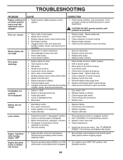
... 4. Operation section. 28 Mower deck not level. 3. Obstruction in the Maintenance section. 3. Replace mower drive belt. 3. Mower deck not level. 4. Level mower deck. 5. Worn, bent or loose blade. 6. Mower drive belt worn. 8. Replace mower drive belt. 9. Switch is shifted into reverse...steering plate (if equipped). 3. See "TO REMOVE WHEEL" in "disengaged" position. 2. Bent blade mandrel. 5. Worn/damaged mower drive belt. 3. Tighten blade bolt. 2. Remove obstruction. 2. Clean underside of grass, leaves, trash under mower. 7. Bad battery cell(s). 2. ...
... 4. Operation section. 28 Mower deck not level. 3. Obstruction in the Maintenance section. 3. Replace mower drive belt. 3. Mower deck not level. 4. Level mower deck. 5. Worn, bent or loose blade. 6. Mower drive belt worn. 8. Replace mower drive belt. 9. Switch is shifted into reverse...steering plate (if equipped). 3. See "TO REMOVE WHEEL" in "disengaged" position. 2. Bent blade mandrel. 5. Worn/damaged mower drive belt. 3. Tighten blade bolt. 2. Remove obstruction. 2. Clean underside of grass, leaves, trash under mower. 7. Bad battery cell(s). 2. ...
Owner Manual
Page 31
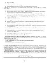
... as belts, pulleys, spindle housings, bearings, blades, rods, height adjusters, caster/anti scalp wheels etc... However, registering your product is listed in the Husqvarna oil label and covered in your product online at www.husqvarna.com. 11. Authorized Husqvarna Servicing Dealer... 43-01 W 2013 IR 31 Reinforced Stamped (Armor Protected) 10 Year Limited & Fabricated Limited Lifetime, Deck Warranties. are for the deck shell only - Documentation Required. Husqvarna encourages you require assistance or have been made. or (q) Continued use of oils that you . In...
... as belts, pulleys, spindle housings, bearings, blades, rods, height adjusters, caster/anti scalp wheels etc... However, registering your product is listed in the Husqvarna oil label and covered in your product online at www.husqvarna.com. 11. Authorized Husqvarna Servicing Dealer... 43-01 W 2013 IR 31 Reinforced Stamped (Armor Protected) 10 Year Limited & Fabricated Limited Lifetime, Deck Warranties. are for the deck shell only - Documentation Required. Husqvarna encourages you require assistance or have been made. or (q) Continued use of oils that you . In...

Owner Manual
Page 33
... Hydro-Gear Distributor network. *** "Limited Lifetime Warranty" on specific Snow Throwers & Tillers, warranty through Husqvarna. ** See reference 4 (b) of the warranty statement. One (1) Year Commercial warranty, parts & labor...catcher, bumper guard accessories, etc. 1 Year No Warranty No Warranty Parts (e.g., belts, blades, etc.) 90 days No Warranty No Warranty Parts & Accessories (if replaced...warranty. Armor Protected Stamped Deck Shell Example Below Fabricated Deck Shell Example Below Armor Protected Stamped Deck Shell Reinforced area Stamped Deck Shell below, NOT ...
... Hydro-Gear Distributor network. *** "Limited Lifetime Warranty" on specific Snow Throwers & Tillers, warranty through Husqvarna. ** See reference 4 (b) of the warranty statement. One (1) Year Commercial warranty, parts & labor...catcher, bumper guard accessories, etc. 1 Year No Warranty No Warranty Parts (e.g., belts, blades, etc.) 90 days No Warranty No Warranty Parts & Accessories (if replaced...warranty. Armor Protected Stamped Deck Shell Example Below Fabricated Deck Shell Example Below Armor Protected Stamped Deck Shell Reinforced area Stamped Deck Shell below, NOT ...


