Owner's Manual
Page 5
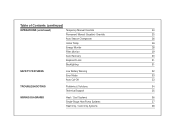
Table of Contents (continued) OPERATIONS (continued) Temporary Manual Override 24 Permanent Manual (Vacation) Override 25 Auto Season Changeover 26 Home Today 26 Energy Monitor 28 Filter Monitor 29 Auto Recovery 30 Keyboard Lock 31 Backlighting 31 SAFETY FEATURES Low Battery Warning 32 Error Mode 33 Auto Cut-Off 33 TROUBLESHOOTING Problems & Solutions 34 Technical Support 35 WIRING DIAGRAMS Heat / Cool Systems 36 Single-Stage Heat Pump Systems 37 Heat Only / Cool Only Systems 38
Table of Contents (continued) OPERATIONS (continued) Temporary Manual Override 24 Permanent Manual (Vacation) Override 25 Auto Season Changeover 26 Home Today 26 Energy Monitor 28 Filter Monitor 29 Auto Recovery 30 Keyboard Lock 31 Backlighting 31 SAFETY FEATURES Low Battery Warning 32 Error Mode 33 Auto Cut-Off 33 TROUBLESHOOTING Problems & Solutions 34 Technical Support 35 WIRING DIAGRAMS Heat / Cool Systems 36 Single-Stage Heat Pump Systems 37 Heat Only / Cool Only Systems 38
Owner's Manual
Page 6
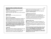
...99°F (37°C), and "LO" will NOT control multi-stage heat pumps or 110/220 Volt systems. INSTALLATION 2 All installation is programmed at your thermostat. These have auxiliary or emergency heat. Note that do not have 24-volt or millivolt control systems and COMPRESSOR... Hunter Thermostat. This can be treated as a Permanent Manual Override. Any change to the set temperature will automatically change to the heating system control. It does not provide a delay when there are power outages. Similarly, the thermostat will also operate single-stage heat pumps ...
...99°F (37°C), and "LO" will NOT control multi-stage heat pumps or 110/220 Volt systems. INSTALLATION 2 All installation is programmed at your thermostat. These have auxiliary or emergency heat. Note that do not have 24-volt or millivolt control systems and COMPRESSOR... Hunter Thermostat. This can be treated as a Permanent Manual Override. Any change to the set temperature will automatically change to the heating system control. It does not provide a delay when there are power outages. Similarly, the thermostat will also operate single-stage heat pumps ...
Owner's Manual
Page 11
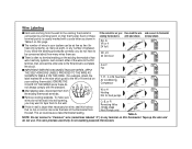
...-battery powered thermostats. s The number of wires in your system can enter the back of the thermostat from O, B, or R Reversing Valve (Single-stage Heat Pumps only) O/B O/B O/B the wall. RH, R, VR or 4 24 Volt RH RH RH If you follow the labeling procedures correctly, you may want... label shown terminal shown terminal points is usually marked with the standard. To make sure RC W or H Heating Not for wires, seal this thermostat. s If hole in wall is larger than necessary for heat pumps W Y/Y1 Y/Y1 W W wires do not fall back into wall opening, you do not use. s...
...-battery powered thermostats. s The number of wires in your system can enter the back of the thermostat from O, B, or R Reversing Valve (Single-stage Heat Pumps only) O/B O/B O/B the wall. RH, R, VR or 4 24 Volt RH RH RH If you follow the labeling procedures correctly, you may want... label shown terminal shown terminal points is usually marked with the standard. To make sure RC W or H Heating Not for wires, seal this thermostat. s If hole in wall is larger than necessary for heat pumps W Y/Y1 Y/Y1 W W wires do not fall back into wall opening, you do not use. s...
Owner's Manual
Page 13
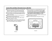
... top of the thermostat cover. s Push excess wire back into hole to prevent interference with your system has an O or B wire, you must move the Heat Pump selector switch to the appropriate position. Connect Wires and Mount Thermostat Cover to Wall Plate s Match and connect the labeled wires to the appropriate coded...
... top of the thermostat cover. s Push excess wire back into hole to prevent interference with your system has an O or B wire, you must move the Heat Pump selector switch to the appropriate position. Connect Wires and Mount Thermostat Cover to Wall Plate s Match and connect the labeled wires to the appropriate coded...
Owner's Manual
Page 14
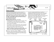
...14-15 Selector Switches In order for this Hunter thermostat to control your Reversing Valve type. HE switch) The factory position for this switch is in this switch is for certain electric systems having a fan relay. If you have a single-stage Heat Pump (no effect in this position if you to...this position if you have a gas furnace or an oil burner. There are also other systems. "HE" position is in COOL mode. If your heat pump system has an "O" wire, slide the switch to OFF before removing the thermostat from the wall. B switch) The factory position for your reversing ...
...14-15 Selector Switches In order for this Hunter thermostat to control your Reversing Valve type. HE switch) The factory position for this switch is in this switch is for certain electric systems having a fan relay. If you have a single-stage Heat Pump (no effect in this position if you to...this position if you have a gas furnace or an oil burner. There are also other systems. "HE" position is in COOL mode. If your heat pump system has an "O" wire, slide the switch to OFF before removing the thermostat from the wall. B switch) The factory position for your reversing ...
Owner's Manual
Page 24
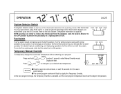
...wait 15 seconds for about 1 second to take full advantage of a rapid system On-Off. You may select COOL, OFF, HEAT, AUTO. For electric heat, air conditioning, and heat pump operation, the Fan will flash to the ON position. The Fan will flash. 72. 7 I. 70. Display will be turned ...on with normal operation of the thermostat. Fan Switch COOL OFF HEAT AUTO The Fan switch should normally be set temperature ...
...wait 15 seconds for about 1 second to take full advantage of a rapid system On-Off. You may select COOL, OFF, HEAT, AUTO. For electric heat, air conditioning, and heat pump operation, the Fan will flash to the ON position. The Fan will flash. 72. 7 I. 70. Display will be turned ...on with normal operation of the thermostat. Fan Switch COOL OFF HEAT AUTO The Fan switch should normally be set temperature ...
Owner's Manual
Page 34
... Cool program temperatures are close, then the thermostat requires a larger room temperature change before the Heat or Cool system turns On - Check the position of the Furnace or Heat Pump selector switch: Normal / O / B. The thermostat may be sure the jumper wire is not in for "AUTO" on .... 8. wait and check. (Compressor protection delay.) 4. Check your system only uses 4-wires, be as much as a 4 minute delay before changing from Heat or Cool. 3. If your circuit breakers and switches to opposite position 1. Press RESET button with a small pin and hold in "HOLD" or "Home ...
... Cool program temperatures are close, then the thermostat requires a larger room temperature change before the Heat or Cool system turns On - Check the position of the Furnace or Heat Pump selector switch: Normal / O / B. The thermostat may be sure the jumper wire is not in for "AUTO" on .... 8. wait and check. (Compressor protection delay.) 4. Check your system only uses 4-wires, be as much as a 4 minute delay before changing from Heat or Cool. 3. If your circuit breakers and switches to opposite position 1. Press RESET button with a small pin and hold in "HOLD" or "Home ...
Owner's Manual
Page 37
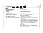
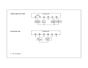
No Connection Single-stage Heat Pump 2-wire Heat Only Jumper RC RH Heat Pump 24V Supply THERMOSTAT G W X Fan Relay Y O/B Compressor Reversing Contactor Valve THERMOSTAT RC RH G W Y O/B X X X X Heat 24V Supply Heat Relay or Valve X -
No Connection Single-stage Heat Pump 2-wire Heat Only Jumper RC RH Heat Pump 24V Supply THERMOSTAT G W X Fan Relay Y O/B Compressor Reversing Contactor Valve THERMOSTAT RC RH G W Y O/B X X X X Heat 24V Supply Heat Relay or Valve X -


