Owner's Manual
Page 3
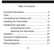
Table of Contents Important Information 5 Tools 6 Uninstalling the Existing Unit 9 Installing the Thermostat 12 Installing the wall plate 14 connecting the wires 15 attaching the thermostat 17 Operation 20 Indicators & Adjustments 22 Troubleshooting 25 Wiring Diagrams 27 3
Table of Contents Important Information 5 Tools 6 Uninstalling the Existing Unit 9 Installing the Thermostat 12 Installing the wall plate 14 connecting the wires 15 attaching the thermostat 17 Operation 20 Indicators & Adjustments 22 Troubleshooting 25 Wiring Diagrams 27 3
Owner's Manual
Page 7
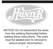
The wires must be labeled prior to removal to ensure proper reconnection. 7 Do not disconnect the wires from the existing thermostat before reading these instructions. NOTICE!
The wires must be labeled prior to removal to ensure proper reconnection. 7 Do not disconnect the wires from the existing thermostat before reading these instructions. NOTICE!
Owner's Manual
Page 9
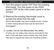
Remove the existing thermostat cover to the back of the wall plate. Turn the power to expose the wires and mounting screws.) 9 Locate, but do not disconnect the wires. (If wires are not visible, they may have doors that must be connected to access the wires from the existing thermostat. Some models may have multiple covers, screws or other locking devices that open to the HVAC system OFF at the main power panel or at the furnace. 2. uninstalling the existing unit 1. Turn the system power OFF from the wall. (Some thermostats may be removed or disengaged.) 3.
Remove the existing thermostat cover to the back of the wall plate. Turn the power to expose the wires and mounting screws.) 9 Locate, but do not disconnect the wires. (If wires are not visible, they may have doors that must be connected to access the wires from the existing thermostat. Some models may have multiple covers, screws or other locking devices that open to the HVAC system OFF at the main power panel or at the furnace. 2. uninstalling the existing unit 1. Turn the system power OFF from the wall. (Some thermostats may be removed or disengaged.) 3.
Owner's Manual
Page 10
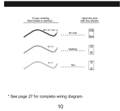
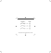
RH / r / vr / 4 w / h g / f label the wire with this sticker: 24 Volt RH heating W fan G G W RH * See page 27 for complete wiring diagram. 10 If your existing thermostat is marked...
RH / r / vr / 4 w / h g / f label the wire with this sticker: 24 Volt RH heating W fan G G W RH * See page 27 for complete wiring diagram. 10 If your existing thermostat is marked...
Owner's Manual
Page 11
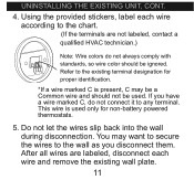
... them. Refer to the chart. (If the terminals are labeled, disconnect each wire according to the existing terminal designation for non-battery powered thermostats. 5. This wire is used only for proper identification. *If a wire marked C is present, C may want to secure the wires to any terminal. uninstalling the existing unit, cont. 4. Do not let the...
... them. Refer to the chart. (If the terminals are labeled, disconnect each wire according to the existing terminal designation for non-battery powered thermostats. 5. This wire is used only for proper identification. *If a wire marked C is present, C may want to secure the wires to any terminal. uninstalling the existing unit, cont. 4. Do not let the...
Owner's Manual
Page 14
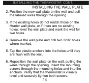
Position the new wall plate on the Hunter wall plate, or if there are flush with the wall. 6. Insert the mounting screws through the mounting holes and into the holes until they are ... and securely tighten both screws. 14 installing the thermostat, cont. Tap the plastic anchors into the anchors. If the existing holes do not match those on the wall and pull the labeled wires through the opening . 3. Reposition the wall plate on the wall, pulling the wires through the opening . INSTALLING THE WALL PLATE...
Position the new wall plate on the Hunter wall plate, or if there are flush with the wall. 6. Insert the mounting screws through the mounting holes and into the holes until they are ... and securely tighten both screws. 14 installing the thermostat, cont. Tap the plastic anchors into the anchors. If the existing holes do not match those on the wall and pull the labeled wires through the opening . 3. Reposition the wall plate on the wall, pulling the wires through the opening . INSTALLING THE WALL PLATE...
Owner's Manual
Page 16
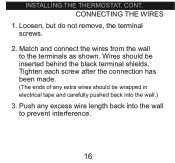
Tighten each screw after the connection has been made. (The ends of any excess wire length back into the wall.) 3. Push any extra wires should be wrapped in electrical tape and carefully pushed back into the wall to the terminals as shown. CONNECTING THE WIRES 1. Loosen, but do not remove, the terminal screws. 2. Wires should be inserted behind the black terminal shields. Match and connect the wires from the wall to prevent interference. 16 installing the thermostat, cont.
Tighten each screw after the connection has been made. (The ends of any excess wire length back into the wall.) 3. Push any extra wires should be wrapped in electrical tape and carefully pushed back into the wall to the terminals as shown. CONNECTING THE WIRES 1. Loosen, but do not remove, the terminal screws. 2. Wires should be inserted behind the black terminal shields. Match and connect the wires from the wall to prevent interference. 16 installing the thermostat, cont.
Owner's Manual
Page 10
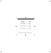
RH / r / vr / 4 w / h g / f label the wire with this sticker: 24 Volt RH heating W fan G G W RH * Vea la página 27 para el digrama eléctrico completo 10 If your existing thermostat is marked...
RH / r / vr / 4 w / h g / f label the wire with this sticker: 24 Volt RH heating W fan G G W RH * Vea la página 27 para el digrama eléctrico completo 10 If your existing thermostat is marked...
Owner's Manual
Page 10
RH / r / vr / 4 w / h g / f label the wire with this sticker: 24 Volt RH heating W fan G G W RH * Voir la page 27 pour le diagramme de câblage complet 10 If your existing thermostat is marked...
RH / r / vr / 4 w / h g / f label the wire with this sticker: 24 Volt RH heating W fan G G W RH * Voir la page 27 pour le diagramme de câblage complet 10 If your existing thermostat is marked...


