
Installation Instructions
Page 2
... working properly, have ionizing-type sensing chambers tend to protect property, not life. If such density levels are made up of smoke detectors, heat detectors, manual pull stations, audible warning devices, and a fire alarm control panel with large amounts of a warning device can provide early warning of service or temporarily disabled...
... working properly, have ionizing-type sensing chambers tend to protect property, not life. If such density levels are made up of smoke detectors, heat detectors, manual pull stations, audible warning devices, and a fire alarm control panel with large amounts of a warning device can provide early warning of service or temporarily disabled...
Installation Instructions
Page 3
... all cable entries from the unit. HPF24S Series Power Supplies - Several different sources of the Microsoft Corporation. ©2010 by Honeywell International Inc. Control unit and associated equipment may be damaged by extreme temperature ranges and humidity. Most devices cannot tolerate more than...from the body. Follow the instructions in which is completely immune from digital apparatus set out in accordance with the instruction manual may damage threads, resulting in -lbs. All components, circuits, system operations, or software functions known to removing or ...
... all cable entries from the unit. HPF24S Series Power Supplies - Several different sources of the Microsoft Corporation. ©2010 by Honeywell International Inc. Control unit and associated equipment may be damaged by extreme temperature ranges and humidity. Most devices cannot tolerate more than...from the body. Follow the instructions in which is completely immune from digital apparatus set out in accordance with the instruction manual may damage threads, resulting in -lbs. All components, circuits, system operations, or software functions known to removing or ...

Installation Instructions
Page 4
... installing and programming the latest features, we make frequent upgrades to commissioning any questions about our online Help or printed manuals, you can email us keep our documentation up-to : FireSystems.TechPubs@honeywell.com Please note this email address is for documentation feedback only. Documentation Feedback Your feedback helps us . Please include...
... installing and programming the latest features, we make frequent upgrades to commissioning any questions about our online Help or printed manuals, you can email us keep our documentation up-to : FireSystems.TechPubs@honeywell.com Please note this email address is for documentation feedback only. Documentation Feedback Your feedback helps us . Please include...

Installation Instructions
Page 9
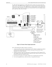
...the four output circuits may be monitored by a 12 VDC or 24 VDC power source. Unless otherwise specified, the information in this manual also applies to the Canadian versions of the power supplies. 1.1 General The HPF24S power supplies can be configured as remotely mounted power ...Appliance Circuits). Alternatively, all four circuits may be configured for shorts). The HPF24S6E and HPF24S8E offer the same features as the HPF24S6 and HPF24S8 respectively. AC fail, battery, charger and ground fault troubles will also be configured as low battery, AC loss, ground fault and battery ...
...the four output circuits may be monitored by a 12 VDC or 24 VDC power source. Unless otherwise specified, the information in this manual also applies to the Canadian versions of the power supplies. 1.1 General The HPF24S power supplies can be configured as remotely mounted power ...Appliance Circuits). Alternatively, all four circuits may be configured for shorts). The HPF24S6E and HPF24S8E offer the same features as the HPF24S6 and HPF24S8 respectively. AC fail, battery, charger and ground fault troubles will also be configured as low battery, AC loss, ground fault and battery ...

Installation Instructions
Page 18
... over (4) standoffs and secure with the module status LED visible through the closed door. Wire module as shown in this figure, refer to the SLC manual appendix, which contains wiring conversion charts for type V and type H modules. 24fsmodltpH.wmf standoff standoff standoff standoff Module Installation 1. P/N 52751:D3 5/11/2010 As an...
... over (4) standoffs and secure with the module status LED visible through the closed door. Wire module as shown in this figure, refer to the SLC manual appendix, which contains wiring conversion charts for type V and type H modules. 24fsmodltpH.wmf standoff standoff standoff standoff Module Installation 1. P/N 52751:D3 5/11/2010 As an...

Installation Instructions
Page 19
.... Your specific application may be used . One such example of conduit is shown below. Any conduit knockouts may require different conduit knockouts to the SLC manual appendix, which contains wiring conversion charts for type V and type H modules. AC Power Nonpower-limited Output Circuits Power-limited Circuits Relay Contacts Nonpower-limited Circuit...
.... Your specific application may be used . One such example of conduit is shown below. Any conduit knockouts may require different conduit knockouts to the SLC manual appendix, which contains wiring conversion charts for type V and type H modules. AC Power Nonpower-limited Output Circuits Power-limited Circuits Relay Contacts Nonpower-limited Circuit...

Installation Instructions
Page 26
A battery fail condition at the power supply - If more than one in this figure, refer to the SLC manual appendix, which NAC circuit is in trouble by setting SW1 DIP switch 4 to the ON position. A monitor module can be configured to delay the reporting ...
A battery fail condition at the power supply - If more than one in this figure, refer to the SLC manual appendix, which NAC circuit is in trouble by setting SW1 DIP switch 4 to the ON position. A monitor module can be configured to delay the reporting ...

Installation Instructions
Page 29
... device associated with Control Module Module has been programmed at the FACP. As an alternative, the trouble contacts at the FACP to (energized) the SLC manual appendix, which contains wiring conversion charts for independent trouble monitoring. 2. EOLR-1 *If the SLC device does not match the one in this figure, refer to...
... device associated with Control Module Module has been programmed at the FACP. As an alternative, the trouble contacts at the FACP to (energized) the SLC manual appendix, which contains wiring conversion charts for independent trouble monitoring. 2. EOLR-1 *If the SLC device does not match the one in this figure, refer to...

Installation Instructions
Page 31
... End-of-Line Resistor across Terminals 5 & 6). When the HPF24S power supply is in this figure, refer to maintain proper supervision. 4. Break wires to the SLC manual appendix, which contains wiring conversion charts for Style Z (Class A) NAC Door Holder Horn/Strobes Alarm Polarity Shown Use listed ELR (4.7K) to terminate Style...
... End-of-Line Resistor across Terminals 5 & 6). When the HPF24S power supply is in this figure, refer to maintain proper supervision. 4. Break wires to the SLC manual appendix, which contains wiring conversion charts for Style Z (Class A) NAC Door Holder Horn/Strobes Alarm Polarity Shown Use listed ELR (4.7K) to terminate Style...

Installation Instructions
Page 32
... Settings 1 & 2 = sync (any setting but OFF/OFF) 3 = OFF (master) 4 = OFF (no sync) FACP FACP NAC End-of Operation In this figure, refer to the SLC manual appendix, which will cause the synchronized power supply output circuits 1 & 2 to turn on. Note: All NACs are supervised and power-limited ELR not required for...
... Settings 1 & 2 = sync (any setting but OFF/OFF) 3 = OFF (master) 4 = OFF (no sync) FACP FACP NAC End-of Operation In this figure, refer to the SLC manual appendix, which will cause the synchronized power supply output circuits 1 & 2 to turn on. Note: All NACs are supervised and power-limited ELR not required for...
Installation Instructions
Page 34
... 24 VDC Resettable Power FACP End-of-Line Resistor supplied with the End-of-Line Resistor referred to in this figure, refer to the SLC manual appendix, which contains wiring conversion charts for module wiring supervision (the ELR value is lost, the Normally Closed power supervision relay contact will open and...
... 24 VDC Resettable Power FACP End-of-Line Resistor supplied with the End-of-Line Resistor referred to in this figure, refer to the SLC manual appendix, which contains wiring conversion charts for module wiring supervision (the ELR value is lost, the Normally Closed power supervision relay contact will open and...

Installation Instructions
Page 35
... the HPF24S Sync In terminals, terminals 1 and 2 on TB4. HPF24S Series Power Supplies - Use only devices from the NAC output. Refer to the FACP user manual to NFPA 72, Chapter 4-4, Visible Characteristics, Public Mode. 2. Refer to determine the source of the sync signal. 4. Refer to the Supervised Master/Slave Connections (Remote...
... the HPF24S Sync In terminals, terminals 1 and 2 on TB4. HPF24S Series Power Supplies - Use only devices from the NAC output. Refer to the FACP user manual to NFPA 72, Chapter 4-4, Visible Characteristics, Public Mode. 2. Refer to determine the source of the sync signal. 4. Refer to the Supervised Master/Slave Connections (Remote...

Installation Instructions
Page 37
... host FACP. Canadian Applications Applications 5.7 Canadian Applications Canadian applications, per ULC, require the following: • The HPF24S power supply must be connected to the SLC manual appendix, which contains wiring conversion charts for all ground fault conditions. P/N 52751:D3 5/11/2010 37 NAC Outputs only Cut JP1 24fsCanadiantpH.wmf Battery - HPF24S...
... host FACP. Canadian Applications Applications 5.7 Canadian Applications Canadian applications, per ULC, require the following: • The HPF24S power supply must be connected to the SLC manual appendix, which contains wiring conversion charts for all ground fault conditions. P/N 52751:D3 5/11/2010 37 NAC Outputs only Cut JP1 24fsCanadiantpH.wmf Battery - HPF24S...