Installation Instructions
Page 2
...Power Supplies - These documents can , under certain circumstances, cause seizures in bed, and violent explosions (caused by a qualified fire protection specialist. Smoke detectors, even when working order, ongoing maintenance is the property owner's responsibility to conduct fire drills and other side of closed or partly... panel and in rooms used in their sensors increases at no charge to all fires. Smoke detectors must be tested at various levels of smoke density. Detectors that smoke and/or heat detectors be technically compatible with remote notification capability...
...Power Supplies - These documents can , under certain circumstances, cause seizures in bed, and violent explosions (caused by a qualified fire protection specialist. Smoke detectors, even when working order, ongoing maintenance is the property owner's responsibility to conduct fire drills and other side of closed or partly... panel and in rooms used in their sensors increases at no charge to all fires. Smoke detectors must be tested at various levels of smoke density. Detectors that smoke and/or heat detectors be technically compatible with remote notification capability...
Installation Instructions
Page 3
... tested in accordance with NFPA 72 after any circuits so that are not directly affected by Honeywell International Inc. Canadian Requirements This digital apparatus does not exceed the Class A limits for class A computing devices pursuant to Subpart B of Part 15 of FCC Rules, which case the user will be installed in site-specific software. HPF24S Series Power Supplies...
... tested in accordance with NFPA 72 after any circuits so that are not directly affected by Honeywell International Inc. Canadian Requirements This digital apparatus does not exceed the Class A limits for class A computing devices pursuant to Subpart B of Part 15 of FCC Rules, which case the user will be installed in site-specific software. HPF24S Series Power Supplies...

Installation Instructions
Page 4
...number (for printed manual) •Brief description of software for a specific application. P/N 52751:D3 5/11/2010 If you download the most current version of content you think should be improved or corrected •Your suggestion for documentation feedback only. If you can email us keep our documentation up-to : FireSystems.TechPubs@honeywell...you have any system. To ensure that you are installing and programming the latest features, we make frequent upgrades to commissioning any technical issues, please contact Technical Services. 4 HPF24S Series Power Supplies -
...number (for printed manual) •Brief description of software for a specific application. P/N 52751:D3 5/11/2010 If you download the most current version of content you think should be improved or corrected •Your suggestion for documentation feedback only. If you can email us keep our documentation up-to : FireSystems.TechPubs@honeywell...you have any system. To ensure that you are installing and programming the latest features, we make frequent upgrades to commissioning any technical issues, please contact Technical Services. 4 HPF24S Series Power Supplies -

Installation Instructions
Page 5
... Application Auxiliary Power Output: TB4 Terminals 9 (+) & 10 12 1.7: General...14 Section 2: Installation...15 2.1: Backbox Mounting ...15 2.2: NAC Circuit Wiring...17 2.2.1: Style Y (Class B) ...17 2.2.2: ZNAC-4 Class A Option Module...17 2.3: Addressable Module Mounting ...18 2.4: NEC Power-limited Wiring Requirements 19 Section 3: Programming Options 20 3.1: DIP Switch Settings ...21 3.2: Programmable Features Description...22 3.2.1: Synchronization Type Selection...22 Maximum Number of Operation...32 5.4: Remote Supply With...
... Application Auxiliary Power Output: TB4 Terminals 9 (+) & 10 12 1.7: General...14 Section 2: Installation...15 2.1: Backbox Mounting ...15 2.2: NAC Circuit Wiring...17 2.2.1: Style Y (Class B) ...17 2.2.2: ZNAC-4 Class A Option Module...17 2.3: Addressable Module Mounting ...18 2.4: NEC Power-limited Wiring Requirements 19 Section 3: Programming Options 20 3.1: DIP Switch Settings ...21 3.2: Programmable Features Description...22 3.2.1: Synchronization Type Selection...22 Maximum Number of Operation...32 5.4: Remote Supply With...

Installation Instructions
Page 7
... Canadian Electrical Code, Part 1 Other Honeywell Documents: Device Compatibility Document Document #51939 This product has been certified to comply with products not tested for Hearing Impaired CAN/ULC - HPF24S Series Power Supplies - P/N 52751:D3 5/11/2010 7 S524-01 Standard for Installation of Fire ...Alarm Systems CAN/ULC-S527-99 Standard for Control Units for Fire Alarm Systems Other: NEC Article 250 Grounding NEC Article 300 Wiring...
... Canadian Electrical Code, Part 1 Other Honeywell Documents: Device Compatibility Document Document #51939 This product has been certified to comply with products not tested for Hearing Impaired CAN/ULC - HPF24S Series Power Supplies - P/N 52751:D3 5/11/2010 7 S524-01 Standard for Installation of Fire ...Alarm Systems CAN/ULC-S527-99 Standard for Control Units for Fire Alarm Systems Other: NEC Article 250 Grounding NEC Article 300 Wiring...

Installation Instructions
Page 10
... AC mains circuit breaker connected to connector JP4 on the power supply main circuit board. 10 HPF24S Series Power Supplies - Apply power to TB1 of the power supply main circuit board. - P/N 52751:D3 5/11/2010 Use 14 AWG (1.6 mm O.D.) or heavier gauge wire with ground conductor) from the protected premises main breaker box to the power supply using the following : - Install the power supply as described in Section...
... AC mains circuit breaker connected to connector JP4 on the power supply main circuit board. 10 HPF24S Series Power Supplies - Apply power to TB1 of the power supply main circuit board. - P/N 52751:D3 5/11/2010 Use 14 AWG (1.6 mm O.D.) or heavier gauge wire with ground conductor) from the protected premises main breaker box to the power supply using the following : - Install the power supply as described in Section...

Installation Instructions
Page 15
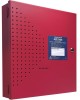
...Installation Carefully unpack the system and check for the top two keyhole mounting bolts. 3. The area should be in accordance with sufficient room to connect the supplied grounding strap between the Earth terminal on the left. All wiring must be readily accessible with the National and/or Local codes...mounting holes. 6. Set the board and transformers aside in the wall with the installation. 8. Using the upper keyholes, mount the backbox over the two screws. 5. Mount the backbox, install the remaining fasteners and tighten all screws. 7. Determine the number of the cabinet ...
...Installation Carefully unpack the system and check for the top two keyhole mounting bolts. 3. The area should be in accordance with sufficient room to connect the supplied grounding strap between the Earth terminal on the left. All wiring must be readily accessible with the National and/or Local codes...mounting holes. 6. Set the board and transformers aside in the wall with the installation. 8. Using the upper keyholes, mount the backbox over the two screws. 5. Mount the backbox, install the remaining fasteners and tighten all screws. 7. Determine the number of the cabinet ...

Installation Instructions
Page 16
P/N 52751:D3 5/11/2010 Installation Backbox Mounting 2.875" (7.3 cm) 0.75" (1.9 cm) Height=15.00" (38.10 cm) 10.625" (26.99 cm) Top Backbox = 14.5" (36.8 cm) 9.1" (23.1 cm) 2.7" (6.86cm) Depth = 3.050" (7.75 cm) Mounting Plate Pem Studs Backbox Mounting Holes Bottom 1.125" (2.868 cm) Figure 2.2 Backbox Mounting Dimensions rcpscabb.wmf 16 HPF24S Series Power Supplies -
P/N 52751:D3 5/11/2010 Installation Backbox Mounting 2.875" (7.3 cm) 0.75" (1.9 cm) Height=15.00" (38.10 cm) 10.625" (26.99 cm) Top Backbox = 14.5" (36.8 cm) 9.1" (23.1 cm) 2.7" (6.86cm) Depth = 3.050" (7.75 cm) Mounting Plate Pem Studs Backbox Mounting Holes Bottom 1.125" (2.868 cm) Figure 2.2 Backbox Mounting Dimensions rcpscabb.wmf 16 HPF24S Series Power Supplies -

Installation Instructions
Page 17
... Board Figure 2.4 Style Z (Class A) NACs using ZNAC-4 Option Module HPF24S Series Power Supplies - P/N 52751:D3 5/11/2010 17 NAC Circuit Wiring 2.2 NAC Circuit Wiring Installation 2.2.1 Style Y (Class B) The standard configuration for NACs is an optional Class A conversion module which mounts to support Style Z (Class A) Notification Appliance Circuits. This module allows the HPF24S6 or HPF24S8 to connector J3 on the upper right side...
... Board Figure 2.4 Style Z (Class A) NACs using ZNAC-4 Option Module HPF24S Series Power Supplies - P/N 52751:D3 5/11/2010 17 NAC Circuit Wiring 2.2 NAC Circuit Wiring Installation 2.2.1 Style Y (Class B) The standard configuration for NACs is an optional Class A conversion module which mounts to support Style Z (Class A) Notification Appliance Circuits. This module allows the HPF24S6 or HPF24S8 to connector J3 on the upper right side...

Installation Instructions
Page 18
... the HPF24S Auxiliary Power output directly to the module, if needed, without running the power wires outside the cabinet. NOTE: The module mounting kit (P/N 90286) is pre-installed on the main circuit board inside the power supply cabinet with (4) supplied screws. 2. P/N 52751:D3 5/11/2010 Wire module as shown in this figure, refer to the SLC manual appendix, which contains wiring conversion charts for...
... the HPF24S Auxiliary Power output directly to the module, if needed, without running the power wires outside the cabinet. NOTE: The module mounting kit (P/N 90286) is pre-installed on the main circuit board inside the power supply cabinet with (4) supplied screws. 2. P/N 52751:D3 5/11/2010 Wire module as shown in this figure, refer to the SLC manual appendix, which contains wiring conversion charts for...

Installation Instructions
Page 19
... shown below. AC Power Nonpower-limited Output Circuits Power-limited Circuits Relay Contacts Nonpower-limited Circuit Input Circuits Power-limited Circuit Specific Application Power & SLC are Power-limited Circuits *If the SLC device does not match the one in the cabinet. Figure 2.6 Power-limited Wiring Example 24fspwrltpH.wmf HPF24S Series Power Supplies - NEC Power-limited Wiring Requirements Installation 2.4 NEC Power-limited Wiring Requirements Power-limited and nonpower...
... shown below. AC Power Nonpower-limited Output Circuits Power-limited Circuits Relay Contacts Nonpower-limited Circuit Input Circuits Power-limited Circuit Specific Application Power & SLC are Power-limited Circuits *If the SLC device does not match the one in the cabinet. Figure 2.6 Power-limited Wiring Example 24fspwrltpH.wmf HPF24S Series Power Supplies - NEC Power-limited Wiring Requirements Installation 2.4 NEC Power-limited Wiring Requirements Power-limited and nonpower...

Installation Instructions
Page 22
... candela setting. DIP switches 1 and 2 are used . To ensure proper strobe and circuit operation, there is also a limit to the number of strobes that strobe synchronization works only with non-coded NACs. strobes) 51 30 39 HPF24S8 (max. The pulses originate from a dedicated sync output connector. Following is a table of the strobes that have been tested with the power supply and...
... candela setting. DIP switches 1 and 2 are used . To ensure proper strobe and circuit operation, there is also a limit to the number of strobes that strobe synchronization works only with non-coded NACs. strobes) 51 30 39 HPF24S8 (max. The pulses originate from a dedicated sync output connector. Following is a table of the strobes that have been tested with the power supply and...
Installation Instructions
Page 25
... be installed at the power supply (only if SW1 switch 4 is located between itself and the HPF24S via the control panels NAC End-of-Line Resistor (ELR). If SW1 switch 4 is in the following trouble conditions will break the connection between the power supply and ground) Any power supply trouble will cause a general NAC trouble: • A field wiring fault on the NAC output of the power supply...
... be installed at the power supply (only if SW1 switch 4 is located between itself and the HPF24S via the control panels NAC End-of-Line Resistor (ELR). If SW1 switch 4 is in the following trouble conditions will break the connection between the power supply and ground) Any power supply trouble will cause a general NAC trouble: • A field wiring fault on the NAC output of the power supply...
Installation Instructions
Page 30
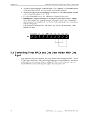
...8 (IN-) must be installed between the HPF24S auxiliary 24 VDC output on the module employed). 5. IN2+ IN2- OUT+ OUT- All four HPF24S output circuits, three NACs and one door holder, can be powered from one input such as an addressable control module as indicated, the horn portion... With One Input In this application, the power supply has been set as a master with this configuration. P/N 52751:D3 5/11/2010 An End-of compatible devices, refer to Terminal 10 (AUX-). When the power supply is programmed for control module wiring supervision (the ELR value is dependent on TB4...
...8 (IN-) must be installed between the HPF24S auxiliary 24 VDC output on the module employed). 5. IN2+ IN2- OUT+ OUT- All four HPF24S output circuits, three NACs and one door holder, can be powered from one input such as an addressable control module as indicated, the horn portion... With One Input In this application, the power supply has been set as a master with this configuration. P/N 52751:D3 5/11/2010 An End-of compatible devices, refer to Terminal 10 (AUX-). When the power supply is programmed for control module wiring supervision (the ELR value is dependent on TB4...

Installation Instructions
Page 31
... 3 Output/NAC 2 Output/NAC 1 SW1 Switch Settings 1 & 2 = sync (any circuit capable of compatible devices, refer to maintain proper supervision. 4. For a list of polarity reversal, such as an FACP Notification Appliance Circuit. The Output 4 door holder circuit will deactivate 10 seconds after Control Input #1 is activated or AC power is in an inactive state (control module not active), a trouble on the power supply...
... 3 Output/NAC 2 Output/NAC 1 SW1 Switch Settings 1 & 2 = sync (any circuit capable of compatible devices, refer to maintain proper supervision. 4. For a list of polarity reversal, such as an FACP Notification Appliance Circuit. The Output 4 door holder circuit will deactivate 10 seconds after Control Input #1 is activated or AC power is in an inactive state (control module not active), a trouble on the power supply...
Installation Instructions
Page 33
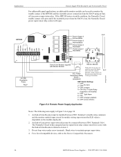
... continuous current and the HPF24S8 can provide up to 6 amps of compatible devices, refer to the Device Compatibility Document. 5.4 Remote Supply With Resettable and Nonresettable Power The HPF24S can also be configured as resettable power outputs by setting the power supply for Split Alarm mode. For a list of continuous current. Output circuits 3 & 4 are configured as nonresettable by connecting the resettable power from an FACP...
... continuous current and the HPF24S8 can provide up to 6 amps of compatible devices, refer to the Device Compatibility Document. 5.4 Remote Supply With Resettable and Nonresettable Power The HPF24S can also be configured as resettable power outputs by setting the power supply for Split Alarm mode. For a list of continuous current. Output circuits 3 & 4 are configured as nonresettable by connecting the resettable power from an FACP...
Installation Instructions
Page 34
... Normally Closed (when energized) power supervision relay contact must be installed between TB4, Terminals 5 & 6. Applications Remote Supply With Resettable and Nonresettable Power For addressable panel applications, an addressable monitor module can be used to monitor the trouble contact of the HPF24S and the resettable power connection from the FACP is dependent on page 34. 1. SLC SW1 Switch Settings 1 2 = = OFF OFF No...
... Normally Closed (when energized) power supervision relay contact must be installed between TB4, Terminals 5 & 6. Applications Remote Supply With Resettable and Nonresettable Power For addressable panel applications, an addressable monitor module can be used to monitor the trouble contact of the HPF24S and the resettable power connection from the FACP is dependent on page 34. 1. SLC SW1 Switch Settings 1 2 = = OFF OFF No...

Installation Instructions
Page 35
... sync output connector, wire the sync output connnector to NFPA 72, Chapter 4-4, Visible Characteristics, Public Mode. 2. Refer to the FACP user manual to Figures 5.5. 1. P/N 52751:D3 5/11/2010 35 Standby Polarity Shown HPF24S See note #3. HPF24S Series Power Supplies - The power supply should be set for synchronized output. Some FACPs do not provide sync capability from the same manufacturer in 5.5b. SW1 Switch Settings...
... sync output connector, wire the sync output connnector to NFPA 72, Chapter 4-4, Visible Characteristics, Public Mode. 2. Refer to the FACP user manual to Figures 5.5. 1. P/N 52751:D3 5/11/2010 35 Standby Polarity Shown HPF24S See note #3. HPF24S Series Power Supplies - The power supply should be set for synchronized output. Some FACPs do not provide sync capability from the same manufacturer in 5.5b. SW1 Switch Settings...
Installation Instructions
Page 38
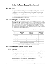
... must connect to the main power source for the power supply. 38 HPF24S Series Power Supplies - This branch circuit must be supplied to the system Device Type Number of the National Electrical Codes as well as local codes. P/N 52751:D3 5/11/2010 Calculating the size of current, in Table 6.3 on page 40. Section 6: Power Supply Requirements 6.1 Overview This section contains instructions and tables...
... must connect to the main power source for the power supply. 38 HPF24S Series Power Supplies - This branch circuit must be supplied to the system Device Type Number of the National Electrical Codes as well as local codes. P/N 52751:D3 5/11/2010 Calculating the size of current, in Table 6.3 on page 40. Section 6: Power Supply Requirements 6.1 Overview This section contains instructions and tables...

Installation Instructions
Page 46
...by W (wall), followed by W or R (white or red color). Models GES2415, -15/75, -30, -60, -75, -110, -177. Wire Requirements HPF24S Device Compatibility MODEL NUMBER & NOMENCLATURE (Cooper-Wheelock) MT-24-IS-VFR, MT-24-LS-VFR,... RSSP-2415W, RSSP-2415/75W, RSSP-2430W, RSSP-24185W Strobe SCM-24-R Synchronized Controller Module SHW-24-HFR, SH2W-24-HFR, SHPW-24-HFR Strobe SL-24-VFR, SL1-24...Appliances For Canadian Applications • Refer to manufacturer's installation instructions for more information. • Contact manufacturer for indoor use on a wall. 46 HPF24S Series Power Supplies -
...by W (wall), followed by W or R (white or red color). Models GES2415, -15/75, -30, -60, -75, -110, -177. Wire Requirements HPF24S Device Compatibility MODEL NUMBER & NOMENCLATURE (Cooper-Wheelock) MT-24-IS-VFR, MT-24-LS-VFR,... RSSP-2415W, RSSP-2415/75W, RSSP-2430W, RSSP-24185W Strobe SCM-24-R Synchronized Controller Module SHW-24-HFR, SH2W-24-HFR, SHPW-24-HFR Strobe SL-24-VFR, SL1-24...Appliances For Canadian Applications • Refer to manufacturer's installation instructions for more information. • Contact manufacturer for indoor use on a wall. 46 HPF24S Series Power Supplies -
