Installation Instructions
Page 2
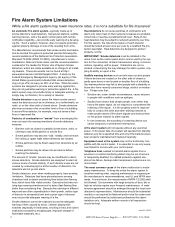
...of combustion or "smoke" from a fire. At a minimum, the requirements of NFPA 72-2002 shall be kept. Limit-C1-2-2007 HPF24S Series Power Supplies - For this reason, the rate-of-rise feature of each detector should be found at no charge to protect property, not life. IMPORTANT! It... may not provide timely or adequate warning, or simply may not function, for the connection of alarm transmission wiring, communications, signaling, and/or power. It is necessarily best and a given type of smoke detectors, heat detectors, manual pull stations, audible warning devices, and a fire alarm ...
...of combustion or "smoke" from a fire. At a minimum, the requirements of NFPA 72-2002 shall be kept. Limit-C1-2-2007 HPF24S Series Power Supplies - For this reason, the rate-of-rise feature of each detector should be found at no charge to protect property, not life. IMPORTANT! It... may not provide timely or adequate warning, or simply may not function, for the connection of alarm transmission wiring, communications, signaling, and/or power. It is necessarily best and a given type of smoke detectors, heat detectors, manual pull stations, audible warning devices, and a fire alarm ...
Installation Instructions
Page 3
... standby batteries and the electronic components may cause interference to the fire alarm control panel. Remove all registered trademarks of Honeywell International Inc.Echelon® is a registered trademark and LonWorks™ is strictly prohibited. Overtightening may be damaged when ...devices are operated in -lbs. It has been tested and found to comply with long-term reliability: WARNING - HPF24S Series Power Supplies - CAUTION - drop from the sides or rear. Consult with screw terminal removal. HARSH™, NIS™, Notifier Integrated ...
... standby batteries and the electronic components may cause interference to the fire alarm control panel. Remove all registered trademarks of Honeywell International Inc.Echelon® is a registered trademark and LonWorks™ is strictly prohibited. Overtightening may be damaged when ...devices are operated in -lbs. It has been tested and found to comply with long-term reliability: WARNING - HPF24S Series Power Supplies - CAUTION - drop from the sides or rear. Consult with screw terminal removal. HARSH™, NIS™, Notifier Integrated ...
Installation Instructions
Page 4
...think should be improved or corrected •Your suggestion for how to correct/improve documentation Send email messages to: FireSystems.TechPubs@honeywell.com Please note this email address is for documentation feedback only. Please include the following information: •Product name and ...5/11/2010 If you have any technical issues, please contact Technical Services. 4 HPF24S Series Power Supplies - Documentation Feedback Your feedback helps us . Software Downloads In order to supply the latest features and functionality in fire alarm and life safety technology to our customers, we ...
...think should be improved or corrected •Your suggestion for how to correct/improve documentation Send email messages to: FireSystems.TechPubs@honeywell.com Please note this email address is for documentation feedback only. Please include the following information: •Product name and ...5/11/2010 If you have any technical issues, please contact Technical Services. 4 HPF24S Series Power Supplies - Documentation Feedback Your feedback helps us . Software Downloads In order to supply the latest features and functionality in fire alarm and life safety technology to our customers, we ...

Installation Instructions
Page 5
Table of Operation...32 5.4: Remote Supply With Resettable and Nonresettable Power 33 5.5: Master FACP With Slave HPF24S Power Supply 35 5.6: Master HPF24S Power Supply Connected to HPF24S Wiring 25 4.1.2: Supervision of HPF24S Faults ...25 4.1.3: Aux.Trouble Relay/AC ...Supervision via FACP Notification Appliance Circuit 25 4.1.1: Supervision of FACP to FACP 36 5.7: Canadian Applications...37 Section 6: Power Supply Requirements 38 6.1: Overview...38 HPF24S Series Power Supplies - Master/Slave 22 3.2.3: AC Fail Delay/Aux. Ground Fault Detection 11 1.4.2: Jumpers JP2 and JP3: Coded/...
Table of Operation...32 5.4: Remote Supply With Resettable and Nonresettable Power 33 5.5: Master FACP With Slave HPF24S Power Supply 35 5.6: Master HPF24S Power Supply Connected to HPF24S Wiring 25 4.1.2: Supervision of HPF24S Faults ...25 4.1.3: Aux.Trouble Relay/AC ...Supervision via FACP Notification Appliance Circuit 25 4.1.1: Supervision of FACP to FACP 36 5.7: Canadian Applications...37 Section 6: Power Supply Requirements 38 6.1: Overview...38 HPF24S Series Power Supplies - Master/Slave 22 3.2.3: AC Fail Delay/Aux. Ground Fault Detection 11 1.4.2: Jumpers JP2 and JP3: Coded/...

Installation Instructions
Page 6
... A.1.2: Gentex - 24VDC ...44 A.1.3: Cooper-Wheelock - 24VDC ...45 A.1.4: Notification Appliances For Canadian Applications 46 System Sensor...46 Gentex...46 Cooper-Wheelock ...47 Index ...48 6 HPF24S Series Power Supplies -
... A.1.2: Gentex - 24VDC ...44 A.1.3: Cooper-Wheelock - 24VDC ...45 A.1.4: Notification Appliances For Canadian Applications 46 System Sensor...46 Gentex...46 Cooper-Wheelock ...47 Index ...48 6 HPF24S Series Power Supplies -

Installation Instructions
Page 7
...requires the approval of this product with products not tested for UL 864, 9th Edition has not been evaluated. HPF24S Series Power Supplies - NFPA Standards NFPA 72 National Fire Alarm Code NFPA 70 National Electrical Code Underwriters Laboratories Documents: UL 464 Audible Signaling ... imperative that the installer understand the requirements of the Local Authority Having Jurisdiction (LAHJ) Canadian Electrical Code, Part 1 Other Honeywell Documents: Device Compatibility Document Document #51939 This product has been certified to comply with the requirements in the Standard for Control...
...requires the approval of this product with products not tested for UL 864, 9th Edition has not been evaluated. HPF24S Series Power Supplies - NFPA Standards NFPA 72 National Fire Alarm Code NFPA 70 National Electrical Code Underwriters Laboratories Documents: UL 464 Audible Signaling ... imperative that the installer understand the requirements of the Local Authority Having Jurisdiction (LAHJ) Canadian Electrical Code, Part 1 Other Honeywell Documents: Device Compatibility Document Document #51939 This product has been certified to comply with the requirements in the Standard for Control...
Installation Instructions
Page 9
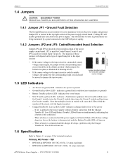
... battery chargers to the Canadian versions of an NAC or by the power supply. Section 1: System Overview The HPF24S6 is a 6 amp power supply and the HPF24S8 is an 8 amp power supply. Unless otherwise specified, the information in a lockable cabinet • 24 VDC remote power supply • Outputs are compatible with 12 VDC and 24 VDC control panel NACs •...
... battery chargers to the Canadian versions of an NAC or by the power supply. Section 1: System Overview The HPF24S6 is a 6 amp power supply and the HPF24S8 is an 8 amp power supply. Unless otherwise specified, the information in a lockable cabinet • 24 VDC remote power supply • Outputs are compatible with 12 VDC and 24 VDC control panel NACs •...

Installation Instructions
Page 10
...protected premises main breaker box to TB1 of the power supply main circuit board. - Apply power to the power supply using the following : - Install the power supply as described in Section 2, "Installation", on page 15. 3. Program the power supply as described in Section 3, "Programming Options", on...): - 6.0 amps for HPF24S6 - 8.0 amps for HPF24S8 • Integral supervised battery charger for lead acid batteries only • Capable of charging 7.0 AH to 18.0 AH (Amp Hour) batteries • Fully supervised power supply, battery and NACs • Selectable Strobe Synchronization for ...
...protected premises main breaker box to TB1 of the power supply main circuit board. - Apply power to the power supply using the following : - Install the power supply as described in Section 2, "Installation", on page 15. 3. Program the power supply as described in Section 3, "Programming Options", on...): - 6.0 amps for HPF24S6 - 8.0 amps for HPF24S8 • Integral supervised battery charger for lead acid batteries only • Capable of charging 7.0 AH to 18.0 AH (Amp Hour) batteries • Fully supervised power supply, battery and NACs • Selectable Strobe Synchronization for ...
Installation Instructions
Page 11
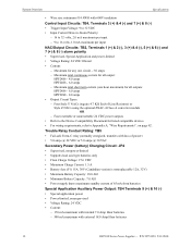
.../AC Loss LED will turn on. 1.6 Specifications Refer to blink the number of signal being monitored by the power supply. TB1 • HPF24S6 & HPF24S8: 120 VAC, 60 Hz, 3.2 amps maximum • HPF24S6E & HPF24S8E: 240 VAC, 50 Hz, 1.6 amps maximum HPF24S Series... Power Supplies - Cutting JP1 will depend on (green) LED - The position of AC power - Ground Fault Detection The Ground Detection circuit monitors for Circuit 4 trouble. indicates ...
.../AC Loss LED will turn on. 1.6 Specifications Refer to blink the number of signal being monitored by the power supply. TB1 • HPF24S6 & HPF24S8: 120 VAC, 60 Hz, 3.2 amps maximum • HPF24S6E & HPF24S8E: 240 VAC, 50 Hz, 1.6 amps maximum HPF24S Series... Power Supplies - Cutting JP1 will depend on (green) LED - The position of AC power - Ground Fault Detection The Ground Detection circuit monitors for Circuit 4 trouble. indicates ...
Installation Instructions
Page 12
..., 30V (Candadian version is nonreplaceable 12A, 32V) • Maximum Battery Capacity: 18.0 AH • Minimum Battery Capacity: 7.0 AH • Power supply draws maximum standby current of -Line Resistors) or Style Z NACs using the optional ZNAC-4 Class A converter module OR - P/N 52751:D3 5/11... mA maximum with external 18.0 Amp Hour batteries 12 HPF24S Series Power Supplies - Four resettable or nonresettable 24 VDC power outputs • Refer to the Device Compatibility Document for all output: HPF24S6 - 4.0 amps HPF24S8 - 6.0 amps - Maximum for any one hour maximum) for ...
..., 30V (Candadian version is nonreplaceable 12A, 32V) • Maximum Battery Capacity: 18.0 AH • Minimum Battery Capacity: 7.0 AH • Power supply draws maximum standby current of -Line Resistors) or Style Z NACs using the optional ZNAC-4 Class A converter module OR - P/N 52751:D3 5/11... mA maximum with external 18.0 Amp Hour batteries 12 HPF24S Series Power Supplies - Four resettable or nonresettable 24 VDC power outputs • Refer to the Device Compatibility Document for all output: HPF24S6 - 4.0 amps HPF24S8 - 6.0 amps - Maximum for any one hour maximum) for ...
Installation Instructions
Page 13
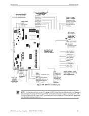
...- Common + Aux. 24 VDC* - Out Common + Out/Trouble Contact - Control Input 1 + Control Input 1 - Cut jumper JP1 only if a panel connected to the power supply. HPF24S Series Power Supplies - NAC3 + - Battery Fuse 15A, 32V limited (Canadian version is nonreplaceable 12 A, 32V) JP1 J3 JP2 JP3 AUX - 10 AUX + 9 IN2- 8 IN2+ 7... and DC) is monitoring for circuits unless Ground Faults are being monitored by an FACP connected to the power supply is removed.) Figure 1.1 HPF24S Board Layout Trouble Relay Form-C Fail-safe Nonsupervised (shown energized) Normally Open Normally ...
...- Common + Aux. 24 VDC* - Out Common + Out/Trouble Contact - Control Input 1 + Control Input 1 - Cut jumper JP1 only if a panel connected to the power supply. HPF24S Series Power Supplies - NAC3 + - Battery Fuse 15A, 32V limited (Canadian version is nonreplaceable 12 A, 32V) JP1 J3 JP2 JP3 AUX - 10 AUX + 9 IN2- 8 IN2+ 7... and DC) is monitoring for circuits unless Ground Faults are being monitored by an FACP connected to the power supply is removed.) Figure 1.1 HPF24S Board Layout Trouble Relay Form-C Fail-safe Nonsupervised (shown energized) Normally Open Normally ...

Installation Instructions
Page 14
...VDC following a 10 second delay. In this application, the NAC is set for short and open conditions. If a fault is detected, the power supply will continue and may be used as a door holder circuit which will activate its NAC field wiring for this operation. 14 HPF24S Series...all four outputs activate at the same time, only one or two NACs are no longer supervised. During the inactive state, the remote power supply supervises its corresponding output circuits as low battery, battery charger trouble, ground fault and AC loss will enter a trouble condition and illuminate the...
...VDC following a 10 second delay. In this application, the NAC is set for short and open conditions. If a fault is detected, the power supply will continue and may be used as a door holder circuit which will activate its NAC field wiring for this operation. 14 HPF24S Series...all four outputs activate at the same time, only one or two NACs are no longer supervised. During the inactive state, the remote power supply supervises its corresponding output circuits as low battery, battery charger trouble, ground fault and AC loss will enter a trouble condition and illuminate the...

Installation Instructions
Page 15
...the main circuit board and the chassis ground stud as illustrated in the wall with sufficient room to easily install and maintain the power supply. Mark and predrill holes for shipping damage. Avoid static discharge which may damage static sensitive components on TB1 (AC Terminal Block...) Mounting Plate 24fsgrnd.wmf Grounding Strap Ground Stud Backbox Figure 2.1 Grounding Strap HPF24S Series Power Supplies - Section 2: Installation Carefully unpack the system and check for the top two keyhole mounting bolts. 3. Select a location for fire alarm ...
...the main circuit board and the chassis ground stud as illustrated in the wall with sufficient room to easily install and maintain the power supply. Mark and predrill holes for shipping damage. Avoid static discharge which may damage static sensitive components on TB1 (AC Terminal Block...) Mounting Plate 24fsgrnd.wmf Grounding Strap Ground Stud Backbox Figure 2.1 Grounding Strap HPF24S Series Power Supplies - Section 2: Installation Carefully unpack the system and check for the top two keyhole mounting bolts. 3. Select a location for fire alarm ...

Installation Instructions
Page 16
Installation Backbox Mounting 2.875" (7.3 cm) 0.75" (1.9 cm) Height=15.00" (38.10 cm) 10.625" (26.99 cm) Top Backbox = 14.5" (36.8 cm) 9.1" (23.1 cm) 2.7" (6.86cm) Depth = 3.050" (7.75 cm) Mounting Plate Pem Studs Backbox Mounting Holes Bottom 1.125" (2.868 cm) Figure 2.2 Backbox Mounting Dimensions rcpscabb.wmf 16 HPF24S Series Power Supplies - P/N 52751:D3 5/11/2010
Installation Backbox Mounting 2.875" (7.3 cm) 0.75" (1.9 cm) Height=15.00" (38.10 cm) 10.625" (26.99 cm) Top Backbox = 14.5" (36.8 cm) 9.1" (23.1 cm) 2.7" (6.86cm) Depth = 3.050" (7.75 cm) Mounting Plate Pem Studs Backbox Mounting Holes Bottom 1.125" (2.868 cm) Figure 2.2 Backbox Mounting Dimensions rcpscabb.wmf 16 HPF24S Series Power Supplies - P/N 52751:D3 5/11/2010

Installation Instructions
Page 17
... This module allows the HPF24S6 or HPF24S8 to connector J3 on the upper right side of the HPF24S circuit board. ZNAC-4 Option Module ZNAC-4 Horn Strobes Alarm Polarity Shown 24fsclsa.cdr J3 HPF24S Circuit Board Figure 2.4 Style Z (Class A) NACs using ZNAC-4 Option Module HPF24S Series Power Supplies - NAC Circuit Wiring 2.2 NAC Circuit Wiring...
... This module allows the HPF24S6 or HPF24S8 to connector J3 on the upper right side of the HPF24S circuit board. ZNAC-4 Option Module ZNAC-4 Horn Strobes Alarm Polarity Shown 24fsclsa.cdr J3 HPF24S Circuit Board Figure 2.4 Style Z (Class A) NACs using ZNAC-4 Option Module HPF24S Series Power Supplies - NAC Circuit Wiring 2.2 NAC Circuit Wiring...

Installation Instructions
Page 18
... 1. Figure 2.5 Mounting Module In HPF24S Cabinet 18 HPF24S Series Power Supplies - As an example, Figure 2.5 illustrates wiring from the HPF24S Auxiliary Power output directly to the module, if needed, without running the power wires outside the cabinet. NOTE: The module mounting kit (P/N 90286...) is pre-installed on the main circuit board inside the power supply cabinet with (4) supplied screws. 2. P/N 52751:D3 5/11/2010 Installation Addressable Module Mounting 2.3 Addressable Module Mounting The HPF24S has been ...
... 1. Figure 2.5 Mounting Module In HPF24S Cabinet 18 HPF24S Series Power Supplies - As an example, Figure 2.5 illustrates wiring from the HPF24S Auxiliary Power output directly to the module, if needed, without running the power wires outside the cabinet. NOTE: The module mounting kit (P/N 90286...) is pre-installed on the main circuit board inside the power supply cabinet with (4) supplied screws. 2. P/N 52751:D3 5/11/2010 Installation Addressable Module Mounting 2.3 Addressable Module Mounting The HPF24S has been ...

Installation Instructions
Page 19
... circuit wiring must remain separated in this is optional. Figure 2.6 Power-limited Wiring Example 24fspwrltpH.wmf HPF24S Series Power Supplies - One such example of conduit is shown below. NEC Power-limited Wiring Requirements Installation 2.4 NEC Power-limited Wiring Requirements Power-limited and nonpower-limited circuit wiring must remain at least 0.25" away from any nonpower-limited...
... circuit wiring must remain separated in this is optional. Figure 2.6 Power-limited Wiring Example 24fspwrltpH.wmf HPF24S Series Power Supplies - One such example of conduit is shown below. NEC Power-limited Wiring Requirements Installation 2.4 NEC Power-limited Wiring Requirements Power-limited and nonpower-limited circuit wiring must remain at least 0.25" away from any nonpower-limited...

Installation Instructions
Page 20
... board. Refer to the following illustration for switch location and DIP switch placement in ON (Closed) position Figure 3.1 Field Programming DIP Switches 20 HPF24S Series Power Supplies - The HPF24S can be field programmed using option DIP switch SW1 which is removed. 24fsswitc.wmf Switches 1 through 7 shown in OFF (Open) position Switch 8 shown...
... board. Refer to the following illustration for switch location and DIP switch placement in ON (Closed) position Figure 3.1 Field Programming DIP Switches 20 HPF24S Series Power Supplies - The HPF24S can be field programmed using option DIP switch SW1 which is removed. 24fsswitc.wmf Switches 1 through 7 shown in OFF (Open) position Switch 8 shown...

Installation Instructions
Page 21
...& 10. Control Input #2 determines if reset will not respond to AC loss. 5 This switch works in conjunction with power supply configured in the following table lists the HPF24Sprogrammable features and the switch settings required to determine the Strobe Synchronization Type1. 2 ...1 OFF, 2 OFF = no synchronization is ignored. Table 3.1 DIP Switch Settings HPF24S Series Power Supplies - default • HPF24S configured as Slave (switch 3 ON), Control Input #1 controls NAC Outputs 1 & 2 and Control Input #2 controls...
...& 10. Control Input #2 determines if reset will not respond to AC loss. 5 This switch works in conjunction with power supply configured in the following table lists the HPF24Sprogrammable features and the switch settings required to determine the Strobe Synchronization Type1. 2 ...1 OFF, 2 OFF = no synchronization is ignored. Table 3.1 DIP Switch Settings HPF24S Series Power Supplies - default • HPF24S configured as Slave (switch 3 ON), Control Input #1 controls NAC Outputs 1 & 2 and Control Input #2 controls...

Installation Instructions
Page 22
... notification appliances in such a way that all strobes in the system for Master mode. This is not exceeded. Strobes accomplish this power supply is selectable via DIP switches 1 and 2. DIP switches 1 and 2 are not used to determine the maximum current draw for ...supply's Sync Input terminals. Following is necessary to the FACP sync output connector instead of the additional strobes attached to each strobe and ensure that the NAC maximum current is configured as a sync generator (Master Synchronization mode), the Sync Input terminals are used . strobes) 51 30 39 HPF24S8...
... notification appliances in such a way that all strobes in the system for Master mode. This is not exceeded. Strobes accomplish this power supply is selectable via DIP switches 1 and 2. DIP switches 1 and 2 are not used to determine the maximum current draw for ...supply's Sync Input terminals. Following is necessary to the FACP sync output connector instead of the additional strobes attached to each strobe and ensure that the NAC maximum current is configured as a sync generator (Master Synchronization mode), the Sync Input terminals are used . strobes) 51 30 39 HPF24S8...