
Installation Instructions
Page 1
...family of low-voltage humidistats/ dehumidistats provide accurate control of whole house humidifiers, dehumidifiers, and ventilators. Failure to make sure the product is suitable for your application. 3. Power supply can be a trained, experienced service technician. Humidity Control Régulateur d'humidit...REMOVAL SLOT M13371 Fig. 2. Before Installing this Product... 1. INSTALLATION INSTRUCTIONS Fig. 1. H8908B,C control. 69-1341EF-01 H8908A,D control. Read these instructions carefully. Disconnect power supply before beginning installation. Check the ratings given in ...
...family of low-voltage humidistats/ dehumidistats provide accurate control of whole house humidifiers, dehumidifiers, and ventilators. Failure to make sure the product is suitable for your application. 3. Power supply can be a trained, experienced service technician. Humidity Control Régulateur d'humidit...REMOVAL SLOT M13371 Fig. 2. Before Installing this Product... 1. INSTALLATION INSTRUCTIONS Fig. 1. H8908B,C control. 69-1341EF-01 H8908A,D control. Read these instructions carefully. Disconnect power supply before beginning installation. Check the ratings given in ...
Installation Instructions
Page 2
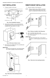
... template with metal shears or tin snips. Run wire to the mounting loca- Cut along the dotted line of wire to properly connect the humidistat. Fig. 4. Run two-fan, low-voltage wire to the mounting location. Leave approximately 6 in . (381 mm) MINIMUM RETURN AIR DUCT...-voltage wire to the mounting location. 69-1341EF-01 2 Leave approximately 6 in the living area. 2. IMPORTANT Use rated 18-22 gauge wire. H8908A/B HUMIDISTAT H8908C/D DEHUMIDISTAT DUCT INSTALLATION 1. Choose a location in . diameter wire hole in duct. 3. tion on the duct. Drill and cut holes in wall. ...
... template with metal shears or tin snips. Run wire to the mounting loca- Cut along the dotted line of wire to properly connect the humidistat. Fig. 4. Run two-fan, low-voltage wire to the mounting location. Leave approximately 6 in . (381 mm) MINIMUM RETURN AIR DUCT...-voltage wire to the mounting location. 69-1341EF-01 2 Leave approximately 6 in the living area. 2. IMPORTANT Use rated 18-22 gauge wire. H8908A/B HUMIDISTAT H8908C/D DEHUMIDISTAT DUCT INSTALLATION 1. Choose a location in . diameter wire hole in duct. 3. tion on the duct. Drill and cut holes in wall. ...
Installation Instructions
Page 3
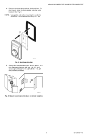
tion. Mount base bracket to the duct or remote loca- H8908A/B HUMIDISTAT H8908C/D DEHUMIDISTAT M24733 Fig. 8. Seal base bracket. 5. Secure the base bracket to duct or remote location. 3 69-1341EF-01 For duct mount, slide the black gasket onto the base bracket. Leave off when mounting to ductwork. NOTE: Use gasket only when mounting the control to a wall. See Fig. 8. M24722 Fig. 9. 4. Remove the base bracket from the humidistat. Secure to the duct with four 1-in. (25 mm) screws (provided) or to the wall with two 1-in. (25 mm) screws (provided).
tion. Mount base bracket to the duct or remote loca- H8908A/B HUMIDISTAT H8908C/D DEHUMIDISTAT M24733 Fig. 8. Seal base bracket. 5. Secure the base bracket to duct or remote location. 3 69-1341EF-01 For duct mount, slide the black gasket onto the base bracket. Leave off when mounting to ductwork. NOTE: Use gasket only when mounting the control to a wall. See Fig. 8. M24722 Fig. 9. 4. Remove the base bracket from the humidistat. Secure to the duct with four 1-in. (25 mm) screws (provided) or to the wall with two 1-in. (25 mm) screws (provided).
Installation Instructions
Page 4
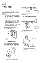
... current sensing relay or sail switch, the humidifier must comply with electronic humidity controls. 6. The remaining two red wires are connected to the base. 69-1341EF-01 4 HUMIDIFIER M24727 Fig. 12. Wire the humidistat. 7. PROVIDE DISCONNECT MEANS AND OVERLOAD PROTECTION AS REQUIRED. 2 24V WIRING. ...humidifier. Press the bottom of the base bracket. M24729 Fig. 14. Attach the humidistat to the control. otherwise, see typical wiring diagrams in to the leads on the H8908 humidistat. IMPORTANT Select models of the transformer to the same power source that services the ...
... current sensing relay or sail switch, the humidifier must comply with electronic humidity controls. 6. The remaining two red wires are connected to the base. 69-1341EF-01 4 HUMIDIFIER M24727 Fig. 12. Wire the humidistat. 7. PROVIDE DISCONNECT MEANS AND OVERLOAD PROTECTION AS REQUIRED. 2 24V WIRING. ...humidifier. Press the bottom of the base bracket. M24729 Fig. 14. Attach the humidistat to the control. otherwise, see typical wiring diagrams in to the leads on the H8908 humidistat. IMPORTANT Select models of the transformer to the same power source that services the ...

Installation Instructions
Page 5
... Wiring H8908 with sail switch and humidifier. Wiring H8908 with steam humidifiers. EQUIPMENT INTERFACE MODULE 1 2 3 C 24 VAC R RC RH CONV. H8908A/B HUMIDISTAT H8908C/D DEHUMIDISTAT H8908 SAIL SWITCH 2 30 20 10 OFF 40 50 60 ON TRANSFORMER 1 L2 L1 (HOT) HUMIDIFIER 1 POWER SUPPLY. TH9421 VISION PRO ...VOLT TRANSFORMER L1 R 30 20 10 OFF 40 50 60 ON H8908 30 20 10 OFF 40 50 60 ON FAN WIRING TERMINALS 1 HUMIDISTAT TERMINALS 1 24V WIRING. Wiring H8908 with VisionPRO® Thermostat for HR150, HR200, ER150 and ER200 Ventilator or DH90 Dehumidifier applications. 1...
... Wiring H8908 with sail switch and humidifier. Wiring H8908 with steam humidifiers. EQUIPMENT INTERFACE MODULE 1 2 3 C 24 VAC R RC RH CONV. H8908A/B HUMIDISTAT H8908C/D DEHUMIDISTAT H8908 SAIL SWITCH 2 30 20 10 OFF 40 50 60 ON TRANSFORMER 1 L2 L1 (HOT) HUMIDIFIER 1 POWER SUPPLY. TH9421 VISION PRO ...VOLT TRANSFORMER L1 R 30 20 10 OFF 40 50 60 ON H8908 30 20 10 OFF 40 50 60 ON FAN WIRING TERMINALS 1 HUMIDISTAT TERMINALS 1 24V WIRING. Wiring H8908 with VisionPRO® Thermostat for HR150, HR200, ER150 and ER200 Ventilator or DH90 Dehumidifier applications. 1...
Installation Instructions
Page 6
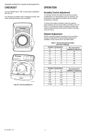
... relative humidity, increase the setpoint approximately three percent relative humidity every 24 hours. Table 1. Recommended Humidity Controller Settings. Recommended settings are available on . Turn humidistat on the control and in the table below. Outdoor Temperature °F °C -20 -29 -10 -23 Recommended...50 40 35 30 25 20 69-1341EF-01 6 H8908A/B HUMIDISTAT H8908C/D DEHUMIDISTAT CHECKOUT Turn the H8908 dial to "ON" to the humidifier. See Fig. 20. OPERATION Humidity Control Adjustment To maintain optimal humidity levels without causing condensation on cold ...
... relative humidity, increase the setpoint approximately three percent relative humidity every 24 hours. Table 1. Recommended Humidity Controller Settings. Recommended settings are available on . Turn humidistat on the control and in the table below. Outdoor Temperature °F °C -20 -29 -10 -23 Recommended...50 40 35 30 25 20 69-1341EF-01 6 H8908A/B HUMIDISTAT H8908C/D DEHUMIDISTAT CHECKOUT Turn the H8908 dial to "ON" to the humidifier. See Fig. 20. OPERATION Humidity Control Adjustment To maintain optimal humidity levels without causing condensation on cold ...

Installation Instructions
Page 8
Rev. 07-07 Registered Trademark © 2007 Honeywell International Inc. 69-1341EF-01 M.S. H8908A/B HUMIDISTAT H8908C/D DEHUMIDISTAT Automation and Control Solutions Honeywell International Inc. Honeywell Limited-Honeywell Limitée 1985 Douglas Drive North 35 Dynamic Drive Golden Valley, MN 55422 Toronto, Ontario M1V 4Z9 customer.honeywell.com ® U.S.
Rev. 07-07 Registered Trademark © 2007 Honeywell International Inc. 69-1341EF-01 M.S. H8908A/B HUMIDISTAT H8908C/D DEHUMIDISTAT Automation and Control Solutions Honeywell International Inc. Honeywell Limited-Honeywell Limitée 1985 Douglas Drive North 35 Dynamic Drive Golden Valley, MN 55422 Toronto, Ontario M1V 4Z9 customer.honeywell.com ® U.S.
