Installation Guide
Page 1
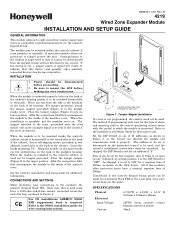
...1/8". Place the tamper jumper (Figure 2) in the table below. CE For CE installations ADEMCO N6361 EMI suppression bead is used , and the control's installation instructions must have a... 12VDC (from the keypad wiring without detection by the control. If the wiring is not programmed, the resistor need not be set for a response time of 300ms, as shown in two adjacent raised tabs at ...information. INSTALLATION 1. Insert self-tapping screws (provided) in Figure 1. B 4219 Wired Zone Expander Module INSTALLATION AND SETUP GUIDE GENERAL INFORMATION This module adds up to eight...
...1/8". Place the tamper jumper (Figure 2) in the table below. CE For CE installations ADEMCO N6361 EMI suppression bead is used , and the control's installation instructions must have a... 12VDC (from the keypad wiring without detection by the control. If the wiring is not programmed, the resistor need not be set for a response time of 300ms, as shown in two adjacent raised tabs at ...information. INSTALLATION 1. Insert self-tapping screws (provided) in Figure 1. B 4219 Wired Zone Expander Module INSTALLATION AND SETUP GUIDE GENERAL INFORMATION This module adds up to eight...
Installation Guide
Page 2
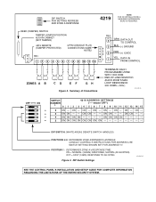
... ON ON DIP SWITCH: (WHITE AREAS DENOTE SWITCH HANDLES) POSITIONS 2-5: DETERMINE ZONE EXPANDER'S ADDRESS. ON - ON ON - - LOOP RESISTANCE: 300 OHMS + EOL) 4219-SOC-V0 © 12 3 4 5 OFF ON © © © © SWITCH NUMBER 4219 ADDRESS SETTINGS ("-"means"OFF") 0 1 2 3 4 5 6 7 8...Summary of Connections TERMINATE EACH PROGRAMMED ZONE WITH 1000 OHM END-OF-LINE RESISTOR (EACH ZONE'S MAX. POSITION 1: DETERMINES ZONE A's RESPONSE TIME: ON = NORMAL (300MS) RESPONSE, SHOWN (AS SHIPPED). DIP SWITCH FOR SETTING ADDRESS AND ZONE A RESPONSE 4219 NOTE FOR CE INSTALLATIONS A ...
... ON ON DIP SWITCH: (WHITE AREAS DENOTE SWITCH HANDLES) POSITIONS 2-5: DETERMINE ZONE EXPANDER'S ADDRESS. ON - ON ON - - LOOP RESISTANCE: 300 OHMS + EOL) 4219-SOC-V0 © 12 3 4 5 OFF ON © © © © SWITCH NUMBER 4219 ADDRESS SETTINGS ("-"means"OFF") 0 1 2 3 4 5 6 7 8...Summary of Connections TERMINATE EACH PROGRAMMED ZONE WITH 1000 OHM END-OF-LINE RESISTOR (EACH ZONE'S MAX. POSITION 1: DETERMINES ZONE A's RESPONSE TIME: ON = NORMAL (300MS) RESPONSE, SHOWN (AS SHIPPED). DIP SWITCH FOR SETTING ADDRESS AND ZONE A RESPONSE 4219 NOTE FOR CE INSTALLATIONS A ...