Installation Guide
Page 1
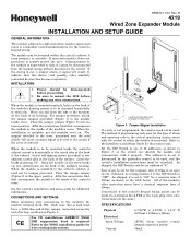
...DIP Switch to be made via 4-terminal block TB2 or the 4-pin plug (wire color connections are provisions to the inside the control's cabinet, mount it properly. Insert self-tapping screws (provided) in the upper position. Hang the module on the screw heads via the control's keypad wiring. CE For CE installations ADEMCO... address to be set for an address of -line resistor supervised zones to be used must be tamper protected. For tamper protection, attach the tamper magnet (provided) (Figure 1) to the inside cover. B 4219 Wired Zone Expander Module INSTALLATION AND SETUP...
...DIP Switch to be made via 4-terminal block TB2 or the 4-pin plug (wire color connections are provisions to the inside the control's cabinet, mount it properly. Insert self-tapping screws (provided) in the upper position. Hang the module on the screw heads via the control's keypad wiring. CE For CE installations ADEMCO... address to be set for an address of -line resistor supervised zones to be used must be tamper protected. For tamper protection, attach the tamper magnet (provided) (Figure 1) to the inside cover. B 4219 Wired Zone Expander Module INSTALLATION AND SETUP...
Installation Guide
Page 2
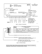
... ON ON ON ON ON ON ON DIP SWITCH: (WHITE AREAS DENOTE SWITCH HANDLES) POSITIONS 2-5: DETERMINE ZONE EXPANDER'S ADDRESS. SWITCH SETTING SHOWN SET FOR ADDRESS "0". ON - CONSULT CONTROL'S INSTRUCTIONS FOR ADDRESS USE. ON ON - - LOOP RESISTANCE: 300 OHMS + EOL) 4219-SOC-V0 © 12 3 4 5 OFF ON © © © © SWITCH NUMBER 4219 ADDRESS SETTINGS ("-"means"OFF") 0 1 2 3 4 5 6 7 8 9 10 11 12 13 14...
... ON ON ON ON ON ON ON DIP SWITCH: (WHITE AREAS DENOTE SWITCH HANDLES) POSITIONS 2-5: DETERMINE ZONE EXPANDER'S ADDRESS. SWITCH SETTING SHOWN SET FOR ADDRESS "0". ON - CONSULT CONTROL'S INSTRUCTIONS FOR ADDRESS USE. ON ON - - LOOP RESISTANCE: 300 OHMS + EOL) 4219-SOC-V0 © 12 3 4 5 OFF ON © © © © SWITCH NUMBER 4219 ADDRESS SETTINGS ("-"means"OFF") 0 1 2 3 4 5 6 7 8 9 10 11 12 13 14...


