User Manual
Page 4
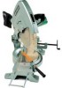
... Nippers, Wooden or Plastic Hammer 1. Loosen the two D4 x 10 -Hd. Machine Screws [48] which fix the Stator Ass'y [46]. Remove the Saw Cover Ass'y [3] and handle Cover [25] by following the disassembly procedures in reverse. As there is another leadwire connected at the Connector [24], cut... off the wires as possible. Tapping Screws [41], and remove the Tail Cover [42] from the Brush Holders [56]. Disconnect the two Stator Brush Terminal ...
... Nippers, Wooden or Plastic Hammer 1. Loosen the two D4 x 10 -Hd. Machine Screws [48] which fix the Stator Ass'y [46]. Remove the Saw Cover Ass'y [3] and handle Cover [25] by following the disassembly procedures in reverse. As there is another leadwire connected at the Connector [24], cut... off the wires as possible. Tapping Screws [41], and remove the Tail Cover [42] from the Brush Holders [56]. Disconnect the two Stator Brush Terminal ...
User Manual
Page 6
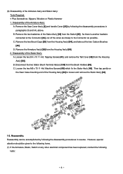
...two M5 x 10 -Hd. Cutting depth adjustment procedures are no exposed wire cores projecting from connectors, terminals, etc. In addition, carefully avoid pinching leadwires between the surface of Vise (B) and Point A (where the Saw Blade intersects the surface of the Turn Table) is obtained, as illustrated... below are no exposed wire cores at the terminals of a 380 mm diameter Saw Blade. On completion of the insulation covering than is not properly ...
...two M5 x 10 -Hd. Cutting depth adjustment procedures are no exposed wire cores projecting from connectors, terminals, etc. In addition, carefully avoid pinching leadwires between the surface of Vise (B) and Point A (where the Saw Blade intersects the surface of the Turn Table) is obtained, as illustrated... below are no exposed wire cores at the terminals of a 380 mm diameter Saw Blade. On completion of the insulation covering than is not properly ...
User Manual
Page 7
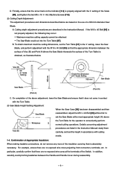
1-5. and Canada Only): WIRING DIAGRAM Armature Ass'y Stator Ass'y Switch Black Brown White White Connector Cord LEADWIRE ARRANGEMENT Noise Suppressor Connector Switch Tube (A) Cord Cord Armor --- 7 --- Wiring Diagrams and Leadwire Arrangements: Perform wiring work as illustrated below. (1) For Products with a Dynamic Brake (115V Specification Products for the U.S.
1-5. and Canada Only): WIRING DIAGRAM Armature Ass'y Stator Ass'y Switch Black Brown White White Connector Cord LEADWIRE ARRANGEMENT Noise Suppressor Connector Switch Tube (A) Cord Cord Armor --- 7 --- Wiring Diagrams and Leadwire Arrangements: Perform wiring work as illustrated below. (1) For Products with a Dynamic Brake (115V Specification Products for the U.S.
User Manual
Page 8
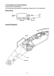
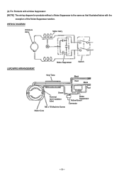
WIRING DIAGRAM Armature Ass'y Stator Ass'y LEADWIRE ARRANGEMENT Noise Suppressor Switch Vinyl Tube Black Red Black Red Green Terminal (w/o insulation tube) M5 x 75 Machine Screw Stator Core Noise Suppressor Yellow/Green Connector --- 8 --- (2) For Products with a Noise Suppressor: [NOTE] The wiring diagram for products without a Noise Suppressor is the same as that illustrated below with the exception of the Noise Suppressor section.
WIRING DIAGRAM Armature Ass'y Stator Ass'y LEADWIRE ARRANGEMENT Noise Suppressor Switch Vinyl Tube Black Red Black Red Green Terminal (w/o insulation tube) M5 x 75 Machine Screw Stator Core Noise Suppressor Yellow/Green Connector --- 8 --- (2) For Products with a Noise Suppressor: [NOTE] The wiring diagram for products without a Noise Suppressor is the same as that illustrated below with the exception of the Noise Suppressor section.


