User Manual
Page 7
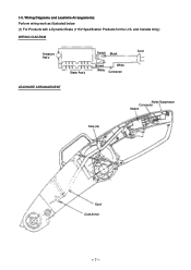
and Canada Only): WIRING DIAGRAM Armature Ass'y Stator Ass'y Switch Black Brown White White Connector Cord LEADWIRE ARRANGEMENT Noise Suppressor Connector Switch Tube (A) Cord Cord Armor --- 7 --- 1-5. Wiring Diagrams and Leadwire Arrangements: Perform wiring work as illustrated below. (1) For Products with a Dynamic Brake (115V Specification Products for the U.S.
and Canada Only): WIRING DIAGRAM Armature Ass'y Stator Ass'y Switch Black Brown White White Connector Cord LEADWIRE ARRANGEMENT Noise Suppressor Connector Switch Tube (A) Cord Cord Armor --- 7 --- 1-5. Wiring Diagrams and Leadwire Arrangements: Perform wiring work as illustrated below. (1) For Products with a Dynamic Brake (115V Specification Products for the U.S.
