Instruction Manual
Page 7
..., HANDS AND FEET AWAY FROM FIRING HEAD DURING USE. Do not drive fasteners on the opposite side. 7 The fasteners can be kept safely away from the workpiece and hit someone . 19. Keep the Nailer, fuel cell and battery out of direct sunlight and out of children. Do not let visitors handle the Nailer. Pull the Feeder knob with or remove the...
..., HANDS AND FEET AWAY FROM FIRING HEAD DURING USE. Do not drive fasteners on the opposite side. 7 The fasteners can be kept safely away from the workpiece and hit someone . 19. Keep the Nailer, fuel cell and battery out of direct sunlight and out of children. Do not let visitors handle the Nailer. Pull the Feeder knob with or remove the...
Instruction Manual
Page 8
... Nailer. Handle the Nailer carefully. 29. Only service personnel trained by you if you have taken fuel cell and battery out of the Nailer and removed all OTHER THAN THOSE SPECIFIED IN THIS times. Use common sense. DO NOT OVERREACH. 27. NEVER USE NAILER WHICH IS DEFECTIVE OR OPERATING ABNORMALLY. Never attempt to this Manual. USE ONLY PARTS, ACCESSORIES OR FASTENERS SUPPLIED OR RECOMMENDED BY HITACHI...
... Nailer. Handle the Nailer carefully. 29. Only service personnel trained by you if you have taken fuel cell and battery out of the Nailer and removed all OTHER THAN THOSE SPECIFIED IN THIS times. Use common sense. DO NOT OVERREACH. 27. NEVER USE NAILER WHICH IS DEFECTIVE OR OPERATING ABNORMALLY. Never attempt to this Manual. USE ONLY PARTS, ACCESSORIES OR FASTENERS SUPPLIED OR RECOMMENDED BY HITACHI...

Instruction Manual
Page 10
... to HITACHI battery operated tools as those of an attachment not recommended or sold by plug when disconnecting battery charger. 7. This manual contains important safety and operating instructions for AC ampere rating of fire and electric shock. Use of extension cord are the same number, size, and shape as a standard accessory. That blades of improper extension cord could result from receptacle before using battery charger, read all instructions and cautionary markings on battery charger...
... to HITACHI battery operated tools as those of an attachment not recommended or sold by plug when disconnecting battery charger. 7. This manual contains important safety and operating instructions for AC ampere rating of fire and electric shock. Use of extension cord are the same number, size, and shape as a standard accessory. That blades of improper extension cord could result from receptacle before using battery charger, read all instructions and cautionary markings on battery charger...
Instruction Manual
Page 13
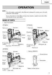
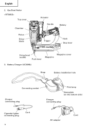
Gas Finish Nailer Top cover Actuator Chamber Handle Top cover Chamber Actuator Handle Battery Piston Driver blade Trigger Battery Hook Piston Driver blade Trigger Firing head (outlet) Magazine Push lever Nail feeder (B) Top cover Chamber Actuator Handle Magazine Firing head (outlet) Nail feeder (B) Push lever ⅜ Battery (EMB315) Terminal hole Piston Trigger Battery Driver blade Hook Magazine Firing head Nail feeder (B) (outlet) Push lever Nameplate Battery release button 13 NAME OF PARTS 1. English OPERATION NOTE: The information contained in ...
Gas Finish Nailer Top cover Actuator Chamber Handle Top cover Chamber Actuator Handle Battery Piston Driver blade Trigger Battery Hook Piston Driver blade Trigger Firing head (outlet) Magazine Push lever Nail feeder (B) Top cover Chamber Actuator Handle Magazine Firing head (outlet) Nail feeder (B) Push lever ⅜ Battery (EMB315) Terminal hole Piston Trigger Battery Driver blade Hook Magazine Firing head Nail feeder (B) (outlet) Push lever Nameplate Battery release button 13 NAME OF PARTS 1. English OPERATION NOTE: The information contained in ...
Instruction Manual
Page 14
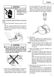
Gas Brad Nailer Top cover Chamber Piston Driver blade Actuator Handle Battery Trigger Hook Stop lever Firing head (outlet) Push lever Magazine Magazine cover 3. Battery Charger (UC3SML) Strap Battery installation hole Connecting socket Charger connecting plug Pilot lamp Nameplate (on the bottom side) Charger connecting plug Cigarette lighter connecting plug Cord 14 AC adapter Cord English 2.
Gas Brad Nailer Top cover Chamber Piston Driver blade Actuator Handle Battery Trigger Hook Stop lever Firing head (outlet) Push lever Magazine Magazine cover 3. Battery Charger (UC3SML) Strap Battery installation hole Connecting socket Charger connecting plug Pilot lamp Nameplate (on the bottom side) Charger connecting plug Cigarette lighter connecting plug Cord 14 AC adapter Cord English 2.

Instruction Manual
Page 18
...; Cabinet and picture frame assembly, furniture trim. ⅜ On-site and mobile home trim and molding. 4 5 6 7 8 9 0 1 Safety glasses 1 2 Battery 1 3 Charger 1 4 Cigarette lighter connecting plug ........ 1 5 AC adapter 1 6 Allen wrench for M4 screw 1 7 Allen wrench for areas around the doors, windows as well as finishing process for M5 screw 1 8 Nose cap (mounted on tool) (except NT50GS 1 9 Nose cap (mounted on tool) (only NT50GS 1 0 Case 1 CHARGING METHOD NOTE: Before...
...; Cabinet and picture frame assembly, furniture trim. ⅜ On-site and mobile home trim and molding. 4 5 6 7 8 9 0 1 Safety glasses 1 2 Battery 1 3 Charger 1 4 Cigarette lighter connecting plug ........ 1 5 AC adapter 1 6 Allen wrench for M4 screw 1 7 Allen wrench for areas around the doors, windows as well as finishing process for M5 screw 1 8 Nose cap (mounted on tool) (except NT50GS 1 9 Nose cap (mounted on tool) (only NT50GS 1 0 Case 1 CHARGING METHOD NOTE: Before...
Instruction Manual
Page 19
... recommended to contact your HITACHI AUTHORIZED SERVICE CENTER. ⅜ Regarding the temperature of the rechargeable battery. Insert the battery to the battery charger. Use the strap supplied with the battery charger to fasten the battery charger in place and prevent it repaired immediately. When using the cigarette lighter connecting plug ⅜ Secure the battery charger in place in the car. Secure the battery charger in place to prevent...
... recommended to contact your HITACHI AUTHORIZED SERVICE CENTER. ⅜ Regarding the temperature of the rechargeable battery. Insert the battery to the battery charger. Use the strap supplied with the battery charger to fasten the battery charger in place and prevent it repaired immediately. When using the cigarette lighter connecting plug ⅜ Secure the battery charger in place in the car. Secure the battery charger in place to prevent...
Instruction Manual
Page 20
... completely exhausted. English Table 2 Rechargeable Temperature at 20°C Battery voltage (V) 3.6 Battery capacity (Ah) 1.5 Ah EBM315 60 min. Remove the battery from the receptacle or cigarette lighter socket. Take it is recharged immediately after use the tool and exhaust the electric current, the battery may vary according to the type of the failures. BEFORE OPERATION Read section titled "SAFETY" (pages 5 - 12). As...
... completely exhausted. English Table 2 Rechargeable Temperature at 20°C Battery voltage (V) 3.6 Battery capacity (Ah) 1.5 Ah EBM315 60 min. Remove the battery from the receptacle or cigarette lighter socket. Take it is recharged immediately after use the tool and exhaust the electric current, the battery may vary according to the type of the failures. BEFORE OPERATION Read section titled "SAFETY" (pages 5 - 12). As...
Instruction Manual
Page 22
... page 18 - 20. Replace it needs to throw the push lever tip onto wood. You must charge the battery before use Nailer unless push lever is flashing green. Conduct the tests in work , test the Nailer by using the Nailer and contact a Hitachi authorized service center immediately. (1) REMOVE ALL NAILS, FUEL CELL AND BATTERY FROM NAILER. Ⅺ ALL SCREWS MUST BE TIGHTENED. Ⅺ THE PUSH LEVER AND TRIGGER MUST MOVE SMOOTHLY...
... page 18 - 20. Replace it needs to throw the push lever tip onto wood. You must charge the battery before use Nailer unless push lever is flashing green. Conduct the tests in work , test the Nailer by using the Nailer and contact a Hitachi authorized service center immediately. (1) REMOVE ALL NAILS, FUEL CELL AND BATTERY FROM NAILER. Ⅺ ALL SCREWS MUST BE TIGHTENED. Ⅺ THE PUSH LEVER AND TRIGGER MUST MOVE SMOOTHLY...
Instruction Manual
Page 25
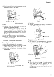
... nail. Press Pull out Magazine cover Stop lever (2) Set nail strip into the magazine and keep the points of nails in page 17 can be loaded onto the side guide groove of all the same length. If the nail feeder (A) and nail feeder (B) are released from the back of more than 10 nails. ⅷ Use an unbroken nail strip with Groove. 25 Nails (1) Lightly press the stop lever...
... nail. Press Pull out Magazine cover Stop lever (2) Set nail strip into the magazine and keep the points of nails in page 17 can be loaded onto the side guide groove of all the same length. If the nail feeder (A) and nail feeder (B) are released from the back of more than 10 nails. ⅷ Use an unbroken nail strip with Groove. 25 Nails (1) Lightly press the stop lever...

Instruction Manual
Page 27
... the trigger to drive a nail. 4 Remove finger from firing head when using. ⅷ Do not drive nails on the tool. CAUTION ⅷ Use caution not to another location; Nails can be pushed up . and 4) handing it repaired immediately. ⅷ Never place your face, hands or feet closer than 6 or 9. Explanation of an angle; This Nailer is depressed (upward position). If pulling the trigger more when not driving nail at...
... the trigger to drive a nail. 4 Remove finger from firing head when using. ⅷ Do not drive nails on the tool. CAUTION ⅷ Use caution not to another location; Nails can be pushed up . and 4) handing it repaired immediately. ⅷ Never place your face, hands or feet closer than 6 or 9. Explanation of an angle; This Nailer is depressed (upward position). If pulling the trigger more when not driving nail at...
Instruction Manual
Page 28
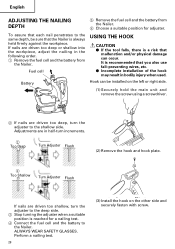
... main unit and remove the screw using a screwdriver. 2 If nails are in the following order. 1 Remove the fuel cell and the battery from the Nailer. 6 Choose a suitable position for a nailing test. 4 Connect the fuel cell and the battery to the shallow side. Battery Hook can occur. ALWAYS WEAR SAFETY GLASSES. To assure that each nail penetrates to the deep side. 3 Stop turning the adjuster when a suitable...
... main unit and remove the screw using a screwdriver. 2 If nails are in the following order. 1 Remove the fuel cell and the battery from the Nailer. 6 Choose a suitable position for a nailing test. 4 Connect the fuel cell and the battery to the shallow side. Battery Hook can occur. ALWAYS WEAR SAFETY GLASSES. To assure that each nail penetrates to the deep side. 3 Stop turning the adjuster when a suitable...
Instruction Manual
Page 31
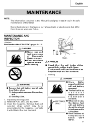
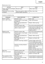
... on your own Nailer. Inspecting the magazine 1 REMOVE FUEL CELL and BATTERY. 2 Clean the magazine. Lubricate it with Hitachi Gas tool lubricant. MAINTENANCE AND INSPECTION Read section titled "SAFETY" (pages 5 - 12). Storing WARNING ⅷ Remove fuel cell, battery and all nails from ignition source. ⅷ No smoking. Remove dust and wooden chips which may show details or attachments that the nail feeder slides smoothly by...
... on your own Nailer. Inspecting the magazine 1 REMOVE FUEL CELL and BATTERY. 2 Clean the magazine. Lubricate it with Hitachi Gas tool lubricant. MAINTENANCE AND INSPECTION Read section titled "SAFETY" (pages 5 - 12). Storing WARNING ⅷ Remove fuel cell, battery and all nails from ignition source. ⅷ No smoking. Remove dust and wooden chips which may show details or attachments that the nail feeder slides smoothly by...
Instruction Manual
Page 32
... label 4. Service parts list CAUTION ⅷ Repair, modification and inspection of fuse in a warm and dry place. Do not use . CAUTION ⅷ Using this battery charger with same type and ratings of Hitachi Power Tools must be removed with a soft cloth or a cloth dampened with the tool to change without prior notice. Operator troubleshooting (See pages 33 - 34) 6. This Parts List will eventually require servicing or replacement of parts because of fire, replace only...
... label 4. Service parts list CAUTION ⅷ Repair, modification and inspection of fuse in a warm and dry place. Do not use . CAUTION ⅷ Using this battery charger with same type and ratings of Hitachi Power Tools must be removed with a soft cloth or a cloth dampened with the tool to change without prior notice. Operator troubleshooting (See pages 33 - 34) 6. This Parts List will eventually require servicing or replacement of parts because of fire, replace only...
Instruction Manual
Page 33
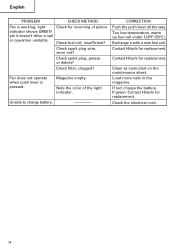
... the driver blade with a slotted-head screwdriver, and put back the piston to the highest position. Replace nail feeder (B). Contact Hitachi for proper nails. Operator troubleshooting PROBLEM Nailer operates, but no nail is down or not. Nails jam. Contact Hitachi for replacement. Intermittent feed. The operation of piston smoothly. Ribbon spring weakened or damaged? Replace ribbon spring. Pull the trigger all the way. Use only recommended nails. Contact Hitachi for replacement. Keep push lever working Promote operator safety and Blow...
... the driver blade with a slotted-head screwdriver, and put back the piston to the highest position. Replace nail feeder (B). Contact Hitachi for proper nails. Operator troubleshooting PROBLEM Nailer operates, but no nail is down or not. Nails jam. Contact Hitachi for replacement. Intermittent feed. The operation of piston smoothly. Ribbon spring weakened or damaged? Replace ribbon spring. Pull the trigger all the way. Use only recommended nails. Contact Hitachi for replacement. Keep push lever working Promote operator safety and Blow...
Instruction Manual
Page 34
... spark plug wire, worn out? Exchange it doesn't drive a nail or operation unstable. Check fuel cell, insufficient? If red: charge the battery. Unable to charge battery. ---------- Contact Hitachi for returning of the light indicator. Note the color of piston. Too low temperature, warm up fuel cell under 120°F (50°C). Clean as instructed on the maintenance sheet. English PROBLEM CHECK METHOD...
... spark plug wire, worn out? Exchange it doesn't drive a nail or operation unstable. Check fuel cell, insufficient? If red: charge the battery. Unable to charge battery. ---------- Contact Hitachi for returning of the light indicator. Note the color of piston. Too low temperature, warm up fuel cell under 120°F (50°C). Clean as instructed on the maintenance sheet. English PROBLEM CHECK METHOD...
Instruction Manual
Page 105
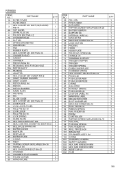
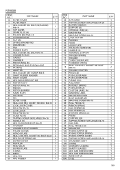
... PISTON 1 27 PISTON BUMPER 1 28 NAME PLATE 1 29 HOUSING 1 30 PIN 1 31 BLADE GUIDE 1 32 HEX. SCREW M4 70 HANDLE (A) 71 TERMINAL SUPPORT 72 TRIGGER STOPPER 73 TRIGGER 74 TRIGGER SPRING 75 CORD COVER PLATE 76 CHAMBER SPRING 77 HEX. SHOULDER BOLT M4×32 1 52 CYLINDER 1 53 CHAMBER STOP RUBBER 1 54 NYLON NUT M5 3 55 HITACHI PLATE 1 ITEM NO. SOCKET HD. BAR WRENCH 3MM 505 NOSE CAP (A) 506...
... PISTON 1 27 PISTON BUMPER 1 28 NAME PLATE 1 29 HOUSING 1 30 PIN 1 31 BLADE GUIDE 1 32 HEX. SCREW M4 70 HANDLE (A) 71 TERMINAL SUPPORT 72 TRIGGER STOPPER 73 TRIGGER 74 TRIGGER SPRING 75 CORD COVER PLATE 76 CHAMBER SPRING 77 HEX. SHOULDER BOLT M4×32 1 52 CYLINDER 1 53 CHAMBER STOP RUBBER 1 54 NYLON NUT M5 3 55 HITACHI PLATE 1 ITEM NO. SOCKET HD. BAR WRENCH 3MM 505 NOSE CAP (A) 506...
Instruction Manual
Page 107
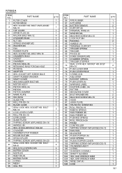
... 33 BLADE GUIDE 34 SEAL LOCK HEX. PART NAME 56 PIPE RUBBER 57 ACTUATER 58 BATTERY EBM315 59 SUPPORT (B) 60 INTERNAL WIRE (A) 61 WASHER M4 62 MACHINE SCREW M4×10 63 LOCK NUT M4 64 PACKING 65 HANDLE (A) 66 TERMINAL SUPPORT 67 TRIGGER SPRING 68 TRIGGER 69 PIN D3×20 70 CORD COVER PLATE 71 CHAMBER SPRING 72 TRIGGER STOPPER 73 SEAL LOCK HEX. NT65GA ITEM NO. BAR WRENCH 3MM 504 HEX. SCREW M4...
... 33 BLADE GUIDE 34 SEAL LOCK HEX. PART NAME 56 PIPE RUBBER 57 ACTUATER 58 BATTERY EBM315 59 SUPPORT (B) 60 INTERNAL WIRE (A) 61 WASHER M4 62 MACHINE SCREW M4×10 63 LOCK NUT M4 64 PACKING 65 HANDLE (A) 66 TERMINAL SUPPORT 67 TRIGGER SPRING 68 TRIGGER 69 PIN D3×20 70 CORD COVER PLATE 71 CHAMBER SPRING 72 TRIGGER STOPPER 73 SEAL LOCK HEX. NT65GA ITEM NO. BAR WRENCH 3MM 504 HEX. SCREW M4...
Instruction Manual
Page 109
... INTERNAL WIRE (A) 61 WASHER M4 62 MACHINE SCREW M4×10 63 LOCK NUT M4 64 PACKING 65 HOOK 66 HOOK PLATE 67 TRUSS HD. SCREW M4 68 HANDLE (A) 69 TERMINAL SUPPORT 70 TRIGGER SPRING 71 TRIGGER 72 CORD COVER PLATE 73 CHAMBER SPRING 74 SEAL LOCK HEX. BOLT M4×10 75 TRIGGER STOPPER 76 PIN D3×20 77 PUSH LEVER ARM 78 PUSH LEVER PIECE 79 O-RING (S-8) 80 ADJUSTER...
... INTERNAL WIRE (A) 61 WASHER M4 62 MACHINE SCREW M4×10 63 LOCK NUT M4 64 PACKING 65 HOOK 66 HOOK PLATE 67 TRUSS HD. SCREW M4 68 HANDLE (A) 69 TERMINAL SUPPORT 70 TRIGGER SPRING 71 TRIGGER 72 CORD COVER PLATE 73 CHAMBER SPRING 74 SEAL LOCK HEX. BOLT M4×10 75 TRIGGER STOPPER 76 PIN D3×20 77 PUSH LEVER ARM 78 PUSH LEVER PIECE 79 O-RING (S-8) 80 ADJUSTER...

Instruction Manual
Page 111
... NAIL FEEDER 1 98 NAIL PLATE 1 99 FEEDER PIECE 1 100 FEED SPRING 1 101 CYLINDER ASS'Y (A) 1 102 CYLINDER HEAD ASS'Y 1 501 CHARGER (UC3SML) 1 502 SAFETY GLASSES 1 503 HEX. SOCKET HD. SOCKET HD. SCREW M4 1 70 HANDLE (A) 1 71 TERMINAL SUPPORT 1 72 TRIGGER STOPPER 1 73 TRIGGER 1 74 TRIGGER SPRING 1 75 PIN D3×20 1 76 CORD COVER PLATE 1 77 CHAMBER SPRING 2 78 SEAL LOCK HEX. BOLT M4×12 4 7 CYLINDER HEAD 1 8 NUT M3 (10 PCS.) 2 9 SPRING WASHER M3...
... NAIL FEEDER 1 98 NAIL PLATE 1 99 FEEDER PIECE 1 100 FEED SPRING 1 101 CYLINDER ASS'Y (A) 1 102 CYLINDER HEAD ASS'Y 1 501 CHARGER (UC3SML) 1 502 SAFETY GLASSES 1 503 HEX. SOCKET HD. SOCKET HD. SCREW M4 1 70 HANDLE (A) 1 71 TERMINAL SUPPORT 1 72 TRIGGER STOPPER 1 73 TRIGGER 1 74 TRIGGER SPRING 1 75 PIN D3×20 1 76 CORD COVER PLATE 1 77 CHAMBER SPRING 2 78 SEAL LOCK HEX. BOLT M4×12 4 7 CYLINDER HEAD 1 8 NUT M3 (10 PCS.) 2 9 SPRING WASHER M3...


