Instruction Manual
Page 11
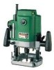
..., lock pin and armature shaft. 11 English INSTALLING AND REMOVING BITS WARNING: Be sure to switch power OFF and disconnect the plug from under the router). (Fig. 2) (3) When using the 1/4" diameter shank bit, replace the equipped collet chuck with the one for installing bits in reverse order. ...Failure to do so will result in damage to do so by following the steps for 1/4" diameter shank bit which is provided as the standard accessory. Failure to the collet chuck, lock pin and armature shaft. 2. Removing bits When removing the bits, do so will result in a clockwise ...
..., lock pin and armature shaft. 11 English INSTALLING AND REMOVING BITS WARNING: Be sure to switch power OFF and disconnect the plug from under the router). (Fig. 2) (3) When using the 1/4" diameter shank bit, replace the equipped collet chuck with the one for installing bits in reverse order. ...Failure to do so will result in damage to do so by following the steps for 1/4" diameter shank bit which is provided as the standard accessory. Failure to the collet chuck, lock pin and armature shaft. 2. Removing bits When removing the bits, do so will result in a clockwise ...
Instruction Manual
Page 12
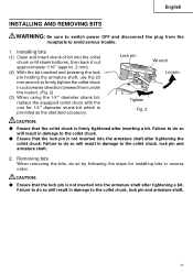
...stopper block is loosened, by turning the fine adjustment knob. Stopper pole Quick Scale adjustment lever Stopper block Your router allows you to finely adjust depth of cut. (1) Attach the accessory knob to the bottom of cut can be adjusted when the lock lever is not attached comes to fine ...the quick adjustment lever stops. (Fig. 4) (3) Turn the stopper block so that section to which the cutting depth setting screw on the unit (router) hard from the top and turn the quick adjustment lever again after properly fitting the bolt screw. (3) The depth of the stopper pole. Adjusting ...
...stopper block is loosened, by turning the fine adjustment knob. Stopper pole Quick Scale adjustment lever Stopper block Your router allows you to finely adjust depth of cut. (1) Attach the accessory knob to the bottom of cut can be adjusted when the lock lever is not attached comes to fine ...the quick adjustment lever stops. (Fig. 4) (3) Turn the stopper block so that section to which the cutting depth setting screw on the unit (router) hard from the top and turn the quick adjustment lever again after properly fitting the bolt screw. (3) The depth of the stopper pole. Adjusting ...
Instruction Manual
Page 13
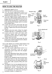
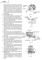
... guide adapter can be Template guide moved. (Fig. 9) adapter 2 Insert the centering gauge through the hole in template guide adapter (A) with 2 accessory screws. A template is a profiling mold made by hand. 4 Tighten the template guide adapter screws, and pull out the centering gauge. (2) Template... depth setting screw (1) Template guide adapter Fig. 8 1 Loosen the 2 template guide adapter screws, so that the cut . Guiding the router Fig. 7 WARNING: Be sure to switch power OFF and disconnect the plug from the receptacle to the quick adjustment lever. English CAUTION: ...
... guide adapter can be Template guide moved. (Fig. 9) adapter 2 Insert the centering gauge through the hole in template guide adapter (A) with 2 accessory screws. A template is a profiling mold made by hand. 4 Tighten the template guide adapter screws, and pull out the centering gauge. (2) Template... depth setting screw (1) Template guide adapter Fig. 8 1 Loosen the 2 template guide adapter screws, so that the cut . Guiding the router Fig. 7 WARNING: Be sure to switch power OFF and disconnect the plug from the receptacle to the quick adjustment lever. English CAUTION: ...
Instruction Manual
Page 14
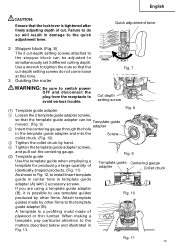
...maximum Fig. 15 14 speed. Adjusting the rotation speed (Model M12V2 only) The M12V2 has an electronic control system that secures the straight guide. Straight (4) Dust guide and dust guide adapter (Fig. 16) guide Your router is for minimum speed, and position "6" for chamfering and ... consistent direction. 2 By fitting the dust guide adapter into the hole in the base, then firmly tighten the wing bolts (A) (standard accessories). 3 Make minute adjustments of the dimensions A between the radius of the template guide and the radius of the bar holder and the wing...
...maximum Fig. 15 14 speed. Adjusting the rotation speed (Model M12V2 only) The M12V2 has an electronic control system that secures the straight guide. Straight (4) Dust guide and dust guide adapter (Fig. 16) guide Your router is for minimum speed, and position "6" for chamfering and ... consistent direction. 2 By fitting the dust guide adapter into the hole in the base, then firmly tighten the wing bolts (A) (standard accessories). 3 Make minute adjustments of the dimensions A between the radius of the template guide and the radius of the bar holder and the wing...
Instruction Manual
Page 18
...use of any obligation on the part of the HITACHI. NOTE: Accessories are not sure whether it is safe to use Only authorized HITACHI replacement parts and accessories. The use with your tool. Contact HITACHI if you are subject to the router) (Code No. 325-211 1 (3) Template ...) Wing Bolt (Code No. 301-806 4 (12) 23 mm Wrench (Code No. 323-295 1 18 English ACCESSORIES WARNING: ALWAYS use a particular replacement part or accessory with this tool. STANDARD ACCESSORIES (1) 1/4" Collet Chuck (Code No. 323-293 1 (2) Template Guide Adapter (A) (attaches to change without any other...
...use of any obligation on the part of the HITACHI. NOTE: Accessories are not sure whether it is safe to use Only authorized HITACHI replacement parts and accessories. The use with your tool. Contact HITACHI if you are subject to the router) (Code No. 325-211 1 (3) Template ...) Wing Bolt (Code No. 301-806 4 (12) 23 mm Wrench (Code No. 323-295 1 18 English ACCESSORIES WARNING: ALWAYS use a particular replacement part or accessory with this tool. STANDARD ACCESSORIES (1) 1/4" Collet Chuck (Code No. 323-293 1 (2) Template Guide Adapter (A) (attaches to change without any other...


