Instruction Manual
Page 11
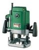
..., lock pin and armature shaft. 11 English INSTALLING AND REMOVING BITS WARNING: Be sure to switch power OFF and disconnect the plug from under the router). (Fig. 2) (3) When using the 1/4" diameter shank bit, replace the equipped collet chuck with the one for installing bits in reverse order. Failure to do so...
..., lock pin and armature shaft. 11 English INSTALLING AND REMOVING BITS WARNING: Be sure to switch power OFF and disconnect the plug from under the router). (Fig. 2) (3) When using the 1/4" diameter shank bit, replace the equipped collet chuck with the one for installing bits in reverse order. Failure to do so...
Instruction Manual
Page 12
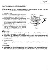
... with the "0" graduation of the stopper pole. Tighten pole lock knob. (7) Loosen the lock lever and press the tool body down on the unit (router) hard from the top and turn the quick adjustment lever again after properly fitting the bolt screw. (3) The depth of cut. (1) Attach the accessory... finely adjust depth of cut can be adjusted when the lock lever is not properly fitted. Stopper pole Quick Scale adjustment lever Stopper block Your router allows you to obtain the desired cutting depth. Loosen the lock lever If this point. (Fig. 5) (5) Tighten pole lock knob. Tighten the ...
... with the "0" graduation of the stopper pole. Tighten pole lock knob. (7) Loosen the lock lever and press the tool body down on the unit (router) hard from the top and turn the quick adjustment lever again after properly fitting the bolt screw. (3) The depth of cut. (1) Attach the accessory... finely adjust depth of cut can be adjusted when the lock lever is not properly fitted. Stopper pole Quick Scale adjustment lever Stopper block Your router allows you to obtain the desired cutting depth. Loosen the lock lever If this point. (Fig. 5) (5) Tighten pole lock knob. Tighten the ...
Instruction Manual
Page 13
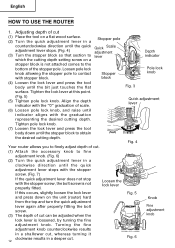
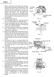
... shaped products. (Fig. 11) Template guide Centering gauge adapter Collet chuck As shown in Fig. 12, to avoid serious trouble. Quick adjustment lever 2. Guiding the router Fig. 7 WARNING: Be sure to switch power OFF and disconnect the plug from the receptacle to install insert template guide in center hole in template...
... shaped products. (Fig. 11) Template guide Centering gauge adapter Collet chuck As shown in Fig. 12, to avoid serious trouble. Quick adjustment lever 2. Guiding the router Fig. 7 WARNING: Be sure to switch power OFF and disconnect the plug from the receptacle to install insert template guide in center hole in template...
Instruction Manual
Page 14
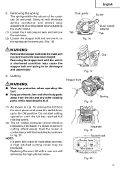
Adjusting the rotation speed (Model M12V2 only) The M12V2 has an electronic control system that secures the straight guide. Feed the router while keeping Wing the guide plane on the surface of the Template finished product will be attached. 4. Straight (4) Dust guide and dust guide adapter (Fig. 16) guide Your router is equipped with a screw...
Adjusting the rotation speed (Model M12V2 only) The M12V2 has an electronic control system that secures the straight guide. Feed the router while keeping Wing the guide plane on the surface of the Template finished product will be attached. 4. Straight (4) Dust guide and dust guide adapter (Fig. 16) guide Your router is equipped with a screw...
Instruction Manual
Page 15
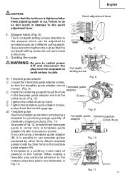
... bolt with a new one will eliminate spring resistance and allows easy adjustment of bit Fig. 20 15 Separate Fig. 19 Router feed Router feed Workpiece Rotation of cutting depth when attaching the router stand. (1) Loosen the 4 sub base screws, and remove the sub base. (2) Loosen the stopper bolt and remove it,... Screw Dust guide adapter Tab Tab Fig. 16 WARNING: Remove the stopper bolt with the feed directions shown in conformance with the main unit (router) fixed at its maximum height. Replacing the worn bit with the unit in Fig. 19, remove the bit from the bits and any other...
... bolt with a new one will eliminate spring resistance and allows easy adjustment of bit Fig. 20 15 Separate Fig. 19 Router feed Router feed Workpiece Rotation of cutting depth when attaching the router stand. (1) Loosen the 4 sub base screws, and remove the sub base. (2) Loosen the stopper bolt and remove it,... Screw Dust guide adapter Tab Tab Fig. 16 WARNING: Remove the stopper bolt with the feed directions shown in conformance with the main unit (router) fixed at its maximum height. Replacing the worn bit with the unit in Fig. 19, remove the bit from the bits and any other...
Instruction Manual
Page 17
...constantly being improved and modified to incorporate the latest technological advancements. code numbers and/or design) may be observed. Maintenance of Hitachi Power Tools must be changed without prior notice. 17 B: Code No. Accordingly, some parts (i.e. English MAINTENANCE AND INSPECTION WARNING:... Parts List will eventually require servicing or replacement of parts because of the power tool. MODIFICATIONS: Hitachi Power Tools are fully tightened. WARNING: Using this router with oil or water. 3. Should any of power tools, the safety regulations and standards prescribed in...
...constantly being improved and modified to incorporate the latest technological advancements. code numbers and/or design) may be observed. Maintenance of Hitachi Power Tools must be changed without prior notice. 17 B: Code No. Accordingly, some parts (i.e. English MAINTENANCE AND INSPECTION WARNING:... Parts List will eventually require servicing or replacement of parts because of the power tool. MODIFICATIONS: Hitachi Power Tools are fully tightened. WARNING: Using this router with oil or water. 3. Should any of power tools, the safety regulations and standards prescribed in...
Instruction Manual
Page 18
... you are not sure whether it is safe to use of any obligation on the part of the HITACHI. NEVER use replacement parts or accessories which are subject to the router) (Code No. 325-211 1 (3) Template Guide Adapter (B) (Code No. 325-224 1 (4) Template Guide (Code No. 956-790 1 (5) Centering Gauge (Code No... 1 (11) Wing Bolt (Code No. 301-806 4 (12) 23 mm Wrench (Code No. 323-295 1 18 NOTE: Accessories are not intended for use Only authorized HITACHI replacement parts and accessories. English ACCESSORIES WARNING: ALWAYS use with your tool.
... you are not sure whether it is safe to use of any obligation on the part of the HITACHI. NEVER use replacement parts or accessories which are subject to the router) (Code No. 325-211 1 (3) Template Guide Adapter (B) (Code No. 325-224 1 (4) Template Guide (Code No. 956-790 1 (5) Centering Gauge (Code No... 1 (11) Wing Bolt (Code No. 301-806 4 (12) 23 mm Wrench (Code No. 323-295 1 18 NOTE: Accessories are not intended for use Only authorized HITACHI replacement parts and accessories. English ACCESSORIES WARNING: ALWAYS use with your tool.
Parts List
Page 1
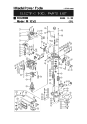
Hitachi Power Tools LIST NO. 0669 ELECTRIC TOOL PARTS LIST ROUTER Model M 12V2 2006 • 2 • 22 (E1) 1 2 3 4 5 6 7 8 9 10 22 21 20 19 18 13 12 11 14 15 14 23 25 24 26 27 40 35 42 21 41 36 37 21 38 43 44 39 16 17 30 31 34 33 32 53 52 44 69 49 70 71 72 73 74 97 75 29 76 28 501 504 502 80 503 81 82 505 506 507 508 509 510 511 77 83 84 85 86 81 87 77 88 87 40 48 45 46 58 44 59 47 57 56 55 54 63 62 61 60 64 5 66 67 68 44 21 37 97 75 78 44 79 95 96 89 90 91 92 93 94 93
Hitachi Power Tools LIST NO. 0669 ELECTRIC TOOL PARTS LIST ROUTER Model M 12V2 2006 • 2 • 22 (E1) 1 2 3 4 5 6 7 8 9 10 22 21 20 19 18 13 12 11 14 15 14 23 25 24 26 27 40 35 42 21 41 36 37 21 38 43 44 39 16 17 30 31 34 33 32 53 52 44 69 49 70 71 72 73 74 97 75 29 76 28 501 504 502 80 503 81 82 505 506 507 508 509 510 511 77 83 84 85 86 81 87 77 88 87 40 48 45 46 58 44 59 47 57 56 55 54 63 62 61 60 64 5 66 67 68 44 21 37 97 75 78 44 79 95 96 89 90 91 92 93 94 93


