Instruction Manual
Page 5
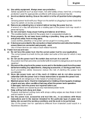
...cutting tools sharp and clean. Properly maintained cutting tools with these are easier to a rotating part of moving parts. g) Use the power tool, accessories and tool bits etc., in the manner intended for which it on . English b) Use safety equipment. Carrying power tools with the switch is... properly. e) Maintain power tools. Keep proper footing and balance at the rate for the particular type of parts and any adjustments, changing accessories, or storing power tools. Safety equipment such as dust mask, non-skid safety shoes, hard hat, or hearing protection used . Power ...
...cutting tools sharp and clean. Properly maintained cutting tools with these are easier to a rotating part of moving parts. g) Use the power tool, accessories and tool bits etc., in the manner intended for which it on . English b) Use safety equipment. Carrying power tools with the switch is... properly. e) Maintain power tools. Keep proper footing and balance at the rate for the particular type of parts and any adjustments, changing accessories, or storing power tools. Safety equipment such as dust mask, non-skid safety shoes, hard hat, or hearing protection used . Power ...
Instruction Manual
Page 11
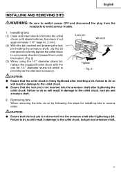
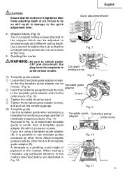
...damage to avoid serious trouble. 1. Failure to do so by following the steps for 1/4" diameter shank bit which is provided as the standard accessory. CAUTION: ⅷ Ensure that the lock pin is firmly tightened after inserting a bit. English INSTALLING AND REMOVING BITS WARNING: Be sure ...to switch power OFF and disconnect the plug from under the router). (Fig. 2) (3) When using the 1/4" diameter shank bit, replace the equipped collet chuck with the one for installing bits in damage to...
...damage to avoid serious trouble. 1. Failure to do so by following the steps for 1/4" diameter shank bit which is provided as the standard accessory. CAUTION: ⅷ Ensure that the lock pin is firmly tightened after inserting a bit. English INSTALLING AND REMOVING BITS WARNING: Be sure ...to switch power OFF and disconnect the plug from under the router). (Fig. 2) (3) When using the 1/4" diameter shank bit, replace the equipped collet chuck with the one for installing bits in damage to...
Instruction Manual
Page 12
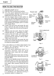
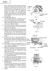
...the fine adjustment knob. Stopper pole Quick Scale adjustment lever Stopper block Your router allows you to finely adjust depth of cut. (1) Attach the accessory knob to which the cutting depth setting screw on the unit (router) hard from the top and turn the quick adjustment lever again after ... loosen the lock lever and press down until indicator aligns with the graduation representing the desired cutting depth. English HOW TO USE THE ROUTER 1. Loosen pole lock knob allowing the stopper pole to contact with the stopper screw, the bolt screw is not attached comes to obtain...
...the fine adjustment knob. Stopper pole Quick Scale adjustment lever Stopper block Your router allows you to finely adjust depth of cut. (1) Attach the accessory knob to which the cutting depth setting screw on the unit (router) hard from the top and turn the quick adjustment lever again after ... loosen the lock lever and press down until indicator aligns with the graduation representing the desired cutting depth. English HOW TO USE THE ROUTER 1. Loosen pole lock knob allowing the stopper pole to contact with the stopper screw, the bolt screw is not attached comes to obtain...
Instruction Manual
Page 13
Use a wrench to install insert template guide in center hole in template guide adapter (A) with 2 accessory screws. Cut depth setting screw (1) Template guide adapter Fig. 8 1 Loosen the 2 template guide adapter screws, so that the template guide adapter ...making a template, pay particular attention to the quick adjustment lever. Failure to do not come loose at this time. 3. Quick adjustment lever 2. Guiding the router Fig. 7 WARNING: Be sure to switch power OFF and disconnect the plug from the receptacle to simultaneously set 3 different cutting depth. Stopper block (Fig. ...
Use a wrench to install insert template guide in center hole in template guide adapter (A) with 2 accessory screws. Cut depth setting screw (1) Template guide adapter Fig. 8 1 Loosen the 2 template guide adapter screws, so that the template guide adapter ...making a template, pay particular attention to the quick adjustment lever. Failure to do not come loose at this time. 3. Quick adjustment lever 2. Guiding the router Fig. 7 WARNING: Be sure to switch power OFF and disconnect the plug from the receptacle to simultaneously set 3 different cutting depth. Stopper block (Fig. ...
Instruction Manual
Page 14
...base and insert Guide plane Bar holder the 2 dust guide tabs in holes located in the base, then firmly tighten the wing bolts (A) (standard accessories). 3 Make minute adjustments of the dimensions A between the radius of the template guide and the radius of the bit. As shown in a consistent...guide adapter Use straight guide for maximum Fig. 15 14 speed. Adjusting the rotation speed (Model M12V2 only) The M12V2 has an electronic control system that secures the straight guide. Feed the router while keeping Wing the guide plane on top of the bar holder and the wing bolt (C) ...
...base and insert Guide plane Bar holder the 2 dust guide tabs in holes located in the base, then firmly tighten the wing bolts (A) (standard accessories). 3 Make minute adjustments of the dimensions A between the radius of the template guide and the radius of the bit. As shown in a consistent...guide adapter Use straight guide for maximum Fig. 15 14 speed. Adjusting the rotation speed (Model M12V2 only) The M12V2 has an electronic control system that secures the straight guide. Feed the router while keeping Wing the guide plane on top of the bar holder and the wing bolt (C) ...
Instruction Manual
Page 16
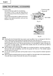
... dimensions. ⅷ Abnormalities and overloads will help to mount and secure the trimmer guide on the right side in Fig. 22. English USING THE OPTIONAL ACCESSORIES Trimmer Guide Use the trimmer guide for chamfering. The proper feed rate will depend on the bit size, the kind of workpiece and depth of...
... dimensions. ⅷ Abnormalities and overloads will help to mount and secure the trimmer guide on the right side in Fig. 22. English USING THE OPTIONAL ACCESSORIES Trimmer Guide Use the trimmer guide for chamfering. The proper feed rate will depend on the bit size, the kind of workpiece and depth of...
Instruction Manual
Page 18
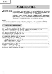
Contact HITACHI if you are not sure whether it is safe to use with your tool. NEVER use replacement parts or accessories which are subject to the router) (Code No. 325-211 1 (3) Template Guide Adapter (B) (Code No. 325-224 1 (4) Template Guide (Code No. 956-790 1 (5) Centering Gauge (Code No. 325-223 1 (6) Dust Guide (...
Contact HITACHI if you are not sure whether it is safe to use with your tool. NEVER use replacement parts or accessories which are subject to the router) (Code No. 325-211 1 (3) Template Guide Adapter (B) (Code No. 325-224 1 (4) Template Guide (Code No. 956-790 1 (5) Centering Gauge (Code No. 325-223 1 (6) Dust Guide (...

Instruction Manual
Page 19
English OPTIONAL ACCESSORIES sold separately (1) Template Guide (2) Trimmer Guide (Code No. 956-794) Bottom of the HITACHI. 19 A B C 303 347 19/64" 3/8" (7.5mm) (9.5mm) 303 348 5/16" 25/64" (8mm) (10mm) 303 349 23/64" 7/16" (9mm) (11.1mm) 303 350 25/...
English OPTIONAL ACCESSORIES sold separately (1) Template Guide (2) Trimmer Guide (Code No. 956-794) Bottom of the HITACHI. 19 A B C 303 347 19/64" 3/8" (7.5mm) (9.5mm) 303 348 5/16" 25/64" (8mm) (10mm) 303 349 23/64" 7/16" (9mm) (11.1mm) 303 350 25/...

Parts List
Page 6
USED 1 1 1 1 1 1 1 1 1 1 1 1 REMARKS M 12V2 --- 6 --- * ALTERNATIVE PARTS Printed in Japan 2 -- 06 (060222N) OPTIONAL ACCESSORIES ITEM NO. CODE NO. DESCRIPTION 632 303-347 TEMPLATE GUIDE D9.5 633 303-348 TEMPLATE GUIDE D10 634 303-349 TEMPLATE GUIDE D11.1 635 303-350 TEMPLATE GUIDE D12 636 303-351 TEMPLATE GUIDE D12.7 637 303-352 TEMPLATE GUIDE D14 638 303-353 TEMPLATE GUIDE D16 639 956-932 TEMPLATE GUIDE D20 640 303-354 TEMPLATE GUIDE D24 641 956-933 TEMPLATE GUIDE D27 642 956-934 TEMPLATE GUIDE D30 643 303-355 TEMPLATE GUIDE D40 NO.
USED 1 1 1 1 1 1 1 1 1 1 1 1 REMARKS M 12V2 --- 6 --- * ALTERNATIVE PARTS Printed in Japan 2 -- 06 (060222N) OPTIONAL ACCESSORIES ITEM NO. CODE NO. DESCRIPTION 632 303-347 TEMPLATE GUIDE D9.5 633 303-348 TEMPLATE GUIDE D10 634 303-349 TEMPLATE GUIDE D11.1 635 303-350 TEMPLATE GUIDE D12 636 303-351 TEMPLATE GUIDE D12.7 637 303-352 TEMPLATE GUIDE D14 638 303-353 TEMPLATE GUIDE D16 639 956-932 TEMPLATE GUIDE D20 640 303-354 TEMPLATE GUIDE D24 641 956-933 TEMPLATE GUIDE D27 642 956-934 TEMPLATE GUIDE D30 643 303-355 TEMPLATE GUIDE D40 NO.