Instruction Manual
Page 4
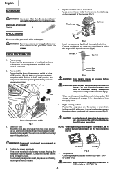
...PARTS AND AIR LEAK. Before further use of the compressor, a guard or other materials which are under the influence of flammable liquids or gases. Risk of children. Do not use , the compressor should be used outdoors, use compressor for lubricating. Compressor produces sparks during operation. Never use outdoors and so marked. 15. Never use compressed air for use compressor...CLEAN. Do not carry and operate the compressor or any part of parts, mounting, air leak, and any parts. HANDLE COMPRESSOR CORRECTLY. This compressor must never be carefully checked to its...
...PARTS AND AIR LEAK. Before further use of the compressor, a guard or other materials which are under the influence of flammable liquids or gases. Risk of children. Do not use , the compressor should be used outdoors, use compressor for lubricating. Compressor produces sparks during operation. Never use outdoors and so marked. 15. Never use compressed air for use compressor...CLEAN. Do not carry and operate the compressor or any part of parts, mounting, air leak, and any parts. HANDLE COMPRESSOR CORRECTLY. This compressor must never be carefully checked to its...
Instruction Manual
Page 5
...will condense in fertilizers - If using the compressor at voltages specified on the safety valve to perform the repair operations correctly. 26. USE ONLY GENUINE HITACHI REPLACEMENT PARTS. Risk of California to discharge the compressed air from the air tank. 33. To drain tank open the... drain cock to cause cancer, birth defects and other reproductive harm. DO NOT STOP COMPRESSOR BY PULLING OUT THE PLUG....
...will condense in fertilizers - If using the compressor at voltages specified on the safety valve to perform the repair operations correctly. 26. USE ONLY GENUINE HITACHI REPLACEMENT PARTS. Risk of California to discharge the compressed air from the air tank. 33. To drain tank open the... drain cock to cause cancer, birth defects and other reproductive harm. DO NOT STOP COMPRESSOR BY PULLING OUT THE PLUG....
Instruction Manual
Page 7
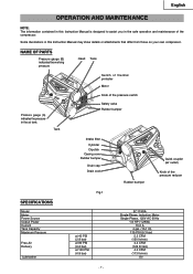
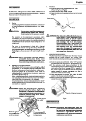
... bumper Intake filter Cylinder Dipstick Casing cover Rubber bumper Drain cap Drain cock Rubber bumper Quick coupler (air outlet) Knob of the compressor. NAME OF PARTS Pressure gauge (B) indicates the working pressure Head Tank Switch of thermal protecter Motor Pressure gauge (A) indicates...Power Source Output Power Current Tank Capacity Maximum Pressure Free Air Delivery Lubrication Fig.1 at 40 PSI (2.8 bar) at 90 PSI (6.2 bar) at 100 PSI (6.9 bar) EC119SA Single-Phase, Induction Motor Single-Phase, 120V AC 60Hz 1.6 HP (1.2KW) 15.0 A 4 gal. (15.1 ltr) 135 PSI (9.3 bar) 5.3 CFM (150...
... bumper Intake filter Cylinder Dipstick Casing cover Rubber bumper Drain cap Drain cock Rubber bumper Quick coupler (air outlet) Knob of the compressor. NAME OF PARTS Pressure gauge (B) indicates the working pressure Head Tank Switch of thermal protecter Motor Pressure gauge (A) indicates...Power Source Output Power Current Tank Capacity Maximum Pressure Free Air Delivery Lubrication Fig.1 at 40 PSI (2.8 bar) at 90 PSI (6.2 bar) at 100 PSI (6.9 bar) EC119SA Single-Phase, Induction Motor Single-Phase, 120V AC 60Hz 1.6 HP (1.2KW) 15.0 A 4 gal. (15.1 ltr) 135 PSI (9.3 bar) 5.3 CFM (150...
Instruction Manual
Page 8
...and stapler. If such a faulty receptacle is in the "ON" position, the compressor will start operating immediately and can lead to the power source requirements specified on the lower part of sufficient thickness and rated capacity (refer page 6). Temperature Operating temperatures are between ...is used, may cause overheating, resulting in temperatures below can cause serious injury. STANDARD ACCESSORY Dipstick 1 Plastic cap Cylinder APPLICATIONS Air source of the pressure switch Fig.2 3. PRIOR TO OPERATION 1. Extension cord When the work area is insufficient, refer to the...
...and stapler. If such a faulty receptacle is in the "ON" position, the compressor will start operating immediately and can lead to the power source requirements specified on the lower part of sufficient thickness and rated capacity (refer page 6). Temperature Operating temperatures are between ...is used, may cause overheating, resulting in temperatures below can cause serious injury. STANDARD ACCESSORY Dipstick 1 Plastic cap Cylinder APPLICATIONS Air source of the pressure switch Fig.2 3. PRIOR TO OPERATION 1. Extension cord When the work area is insufficient, refer to the...
Instruction Manual
Page 9
...air, abrasion particles, rust, etc.. conditions and duration of the nailers, staplers and accessories. If the motor still stops during use . Compressor outlet pressure must be tripped, the compressor will restart only if reset is done. Transport (3) Open the drain cock located at the lower part... page 6 replace with manual reset (push-button), which stops it when the pressure in the air tank - 9 - WARNING: Disconnect the compressor from the power source and remove the compressed air from the receptacle (Fig. 2). 2. A pressure gauge (B) is provided to know when the required...
...air, abrasion particles, rust, etc.. conditions and duration of the nailers, staplers and accessories. If the motor still stops during use . Compressor outlet pressure must be tripped, the compressor will restart only if reset is done. Transport (3) Open the drain cock located at the lower part... page 6 replace with manual reset (push-button), which stops it when the pressure in the air tank - 9 - WARNING: Disconnect the compressor from the power source and remove the compressed air from the receptacle (Fig. 2). 2. A pressure gauge (B) is provided to know when the required...
Instruction Manual
Page 10
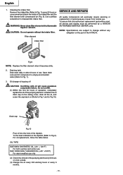
... oil will eventually require servicing or screwdriver to Fig. 1) every 50 hours or SERVICE AND REPAIRS once a week and clean the inside of the HITACHI. liquid or solvent. NOTE: Specifications are subject to Fig.10). Unfasten the oil drain cap on (Refer to Fig.1 and to change -oil... CENTER, only. For oil replacement, follow the table below. To the level indicated on the part of the intake filter and the filter element with compressed air (Fig. 9). Open drain cock and tilt compressor to empty accumulated water (Refer to Fig.4). Drain cap Fig.10 Pour oil into the hole...
... oil will eventually require servicing or screwdriver to Fig. 1) every 50 hours or SERVICE AND REPAIRS once a week and clean the inside of the HITACHI. liquid or solvent. NOTE: Specifications are subject to Fig.10). Unfasten the oil drain cap on (Refer to Fig.1 and to change -oil... CENTER, only. For oil replacement, follow the table below. To the level indicated on the part of the intake filter and the filter element with compressed air (Fig. 9). Open drain cock and tilt compressor to empty accumulated water (Refer to Fig.4). Drain cap Fig.10 Pour oil into the hole...


