
Limited Warranty and Support Guide
Page 6
...warranty service for an extensive description of your proof of the products may be covered by export controls issued by local law, new HP Hardware Products may also have purchased or leased from HP are provided "AS IS" without voiding the warranty. Replacement parts are warranted to... STATUTORY RIGHTS APPLICABLE TO THE SALE OF THIS PRODUCT TO YOU. This Limited Warranty is longer. 4 non-HP products or non-HP branded peripherals. However, non-HP manufacturers and suppliers, or publishers may provide their own warranties directly to the extent permitted by the United States...
...warranty service for an extensive description of your proof of the products may be covered by export controls issued by local law, new HP Hardware Products may also have purchased or leased from HP are provided "AS IS" without voiding the warranty. Replacement parts are warranted to... STATUTORY RIGHTS APPLICABLE TO THE SALE OF THIS PRODUCT TO YOU. This Limited Warranty is longer. 4 non-HP products or non-HP branded peripherals. However, non-HP manufacturers and suppliers, or publishers may provide their own warranties directly to the extent permitted by the United States...

Warranty - Refurbished
Page 6
... or new and used products or parts equivalent to new in performance and reliability or (b) with equivalent products to the HP Hardware Product-such as a condition of the products may be covered by export controls issued by or leased from Hewlett-Packard Company, its authorized service providers offer warranty service for any...
... or new and used products or parts equivalent to new in performance and reliability or (b) with equivalent products to the HP Hardware Product-such as a condition of the products may be covered by export controls issued by or leased from Hewlett-Packard Company, its authorized service providers offer warranty service for any...

Upgrading and Servicing Guide
Page 5
... requires two AAA batteries. The blue activity LED on the wireless receiver illuminates when the synchronization command has been received and goes off the battery cover, remove the old batteries, and insert new alkaline batteries. NOTE: If the synchronization does not work , you may need to 10 seconds. Do not use...
... requires two AAA batteries. The blue activity LED on the wireless receiver illuminates when the synchronization command has been received and goes off the battery cover, remove the old batteries, and insert new alkaline batteries. NOTE: If the synchronization does not work , you may need to 10 seconds. Do not use...

Upgrading and Servicing Guide
Page 8
... the computer. 3 Unplug the computer by touching the metal cage of the computer. 5 Set down on the soft surface. 6 584963-001 - WARNING: z Never open the cover with the power cord attached or power applied. Computer Preparation 1 Remove any internal parts or electronic components. Discharge static electricity by disconnecting the power cord...
... the computer. 3 Unplug the computer by touching the metal cage of the computer. 5 Set down on the soft surface. 6 584963-001 - WARNING: z Never open the cover with the power cord attached or power applied. Computer Preparation 1 Remove any internal parts or electronic components. Discharge static electricity by disconnecting the power cord...

Upgrading and Servicing Guide
Page 9
Upgrading or Replacing Memory 7 Removing the Memory 6 Lift the plastic shield on the back of the computer stand. 9 Use your fingers to press outwards on the tabs on the left and right sides of a memory card to release it. 7 Use a torx or flat-head screwdriver to remove the screw that secures the right cover. 10 Hold the card by its edges, and remove it from the compartment. 8 Slide the right cover off. 584963-001 -
Upgrading or Replacing Memory 7 Removing the Memory 6 Lift the plastic shield on the back of the computer stand. 9 Use your fingers to press outwards on the tabs on the left and right sides of a memory card to release it. 7 Use a torx or flat-head screwdriver to remove the screw that secures the right cover. 10 Hold the card by its edges, and remove it from the compartment. 8 Slide the right cover off. 584963-001 -

Upgrading and Servicing Guide
Page 10
Installing a New Memory Card 1 Orient the new card so that the notch on the edge of the card faces forward and is on the right. 4 Slide the right cover into place. 2 Holding the card by its edges, slide it all the way into the slot. 5 Replace the right cover screw. 3 Gently push downward on the card to snap it into place. 6 Reconnect any cables that were disconnected for this procedure. 8 584963-001 - Upgrading or Replacing Memory
Installing a New Memory Card 1 Orient the new card so that the notch on the edge of the card faces forward and is on the right. 4 Slide the right cover into place. 2 Holding the card by its edges, slide it all the way into the slot. 5 Replace the right cover screw. 3 Gently push downward on the card to snap it into place. 6 Reconnect any cables that were disconnected for this procedure. 8 584963-001 - Upgrading or Replacing Memory
Upgrading and Servicing Guide
Page 14
... electricity by disconnecting the power cord from the back of the computer. 4 Unplug all attached cables from scratches or other damage. WARNING: z Never open the cover with the power cord attached or power applied.
... electricity by disconnecting the power cord from the back of the computer. 4 Unplug all attached cables from scratches or other damage. WARNING: z Never open the cover with the power cord attached or power applied.

Upgrading and Servicing Guide
Page 15
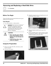
TIP: You do not need to remove this screw, only loosen it in order to release the hard disk drive cage. 7 Use a torx or flat-head screwdriver to remove the screw that secures the left cover off. 11 Disconnect the cable connector from the back of the hard disk drive cage. Removing and Replacing a Hard Disk Drive 13 Removing the Hard Disk Drive 6 Lift the plastic shield on the wire handle, and pull the hard disk drive cage out. 8 Slide the left cover. 10 Lift up on the back of the computer stand. 9 Loosen the screw at the bottom of the hard disk drive. 584963-001 -
TIP: You do not need to remove this screw, only loosen it in order to release the hard disk drive cage. 7 Use a torx or flat-head screwdriver to remove the screw that secures the left cover off. 11 Disconnect the cable connector from the back of the hard disk drive cage. Removing and Replacing a Hard Disk Drive 13 Removing the Hard Disk Drive 6 Lift the plastic shield on the wire handle, and pull the hard disk drive cage out. 8 Slide the left cover. 10 Lift up on the back of the computer stand. 9 Loosen the screw at the bottom of the hard disk drive. 584963-001 -

Upgrading and Servicing Guide
Page 17
4 Align the wheels on each side of the top of the hard disk drive cage with the slots in the hard disk drive bay, and insert the hard disk drive. 7 Slide the left cover into place. 5 Press down on the hard disk cage handle to snap it into place. 8 Replace the left cover screw. 6 Tighten the captive screw on the hard disk drive cage. 9 Reconnect any cables that were disconnected for this procedure. 10 Plug the power cord into the back of the computer and then into the power source. 584963-001 - Removing and Replacing a Hard Disk Drive 15
4 Align the wheels on each side of the top of the hard disk drive cage with the slots in the hard disk drive bay, and insert the hard disk drive. 7 Slide the left cover into place. 5 Press down on the hard disk cage handle to snap it into place. 8 Replace the left cover screw. 6 Tighten the captive screw on the hard disk drive cage. 9 Reconnect any cables that were disconnected for this procedure. 10 Plug the power cord into the back of the computer and then into the power source. 584963-001 - Removing and Replacing a Hard Disk Drive 15
Upgrading and Servicing Guide
Page 20
... back of the computer. 5 Set down a blanket, towel, or other soft cloth to protect the screen from scratches or other damage. WARNING: z Never open the cover with the power cord attached or power applied. Computer Preparation 1 Remove any media (CD, DVD, and memory cards) from the computer. 2 Shut down on the...
... back of the computer. 5 Set down a blanket, towel, or other soft cloth to protect the screen from scratches or other damage. WARNING: z Never open the cover with the power cord attached or power applied. Computer Preparation 1 Remove any media (CD, DVD, and memory cards) from the computer. 2 Shut down on the...

Upgrading and Servicing Guide
Page 21
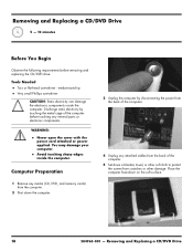
Removing and Replacing a CD/DVD Drive 19 TIP: You do not need to remove this screw, only loosen it in order to release the CD/DVD drive cage. 7 Use a torx or flat-head screwdriver to disengage the CD/DVD drive cage. 8 Slide the left cover. 10 Grasp the tab at the back of the arrow to remove the screw that secures the left cover off. 584963-001 - Removing the CD/DVD Drive 6 Lift the plastic shield on the back of the computer stand. 9 Loosen the screw at the top of the CD/DVD drive cage, and slide it in the direction of the CD/DVD drive cage.
Removing and Replacing a CD/DVD Drive 19 TIP: You do not need to remove this screw, only loosen it in order to release the CD/DVD drive cage. 7 Use a torx or flat-head screwdriver to disengage the CD/DVD drive cage. 8 Slide the left cover. 10 Grasp the tab at the back of the arrow to remove the screw that secures the left cover off. 584963-001 - Removing the CD/DVD Drive 6 Lift the plastic shield on the back of the computer stand. 9 Loosen the screw at the top of the CD/DVD drive cage, and slide it in the direction of the CD/DVD drive cage.

Upgrading and Servicing Guide
Page 24
Removing and Replacing a CD/DVD Drive 6 Slide the left cover into place. 8 Reconnect any cables that were disconnected for this procedure. 9 Plug the power cord into the back of the computer and then into the power source. 7 Replace the left cover screw. 10 Return the computer to the upright position and turn on the computer. 22 584963-001 -
Removing and Replacing a CD/DVD Drive 6 Slide the left cover into place. 8 Reconnect any cables that were disconnected for this procedure. 9 Plug the power cord into the back of the computer and then into the power source. 7 Replace the left cover screw. 10 Return the computer to the upright position and turn on the computer. 22 584963-001 -
HP VESA Adapter Assembly Installation Guide
Page 1
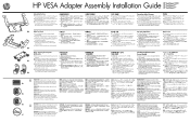
... the touch screen surface from the electrical outlet. 4. CAUTION: The TouchSmart PC is designed to be sure to disconnect the power cord from the power source before removing the memory cover or back cover. Third-party wall-mounting device (sold separately) 2 Before Opening the... (0.3-inch) screws 4. Place the computer facedown on the computer (recommended) !! Shut down the computer using the operating system. 3. HP VESA Adapter Assembly Installation Guide Included in damage to the hardware components. Two leg inserts with four 8-mm (0.3-inch) screws for detailed...
... the touch screen surface from the electrical outlet. 4. CAUTION: The TouchSmart PC is designed to be sure to disconnect the power cord from the power source before removing the memory cover or back cover. Third-party wall-mounting device (sold separately) 2 Before Opening the... (0.3-inch) screws 4. Place the computer facedown on the computer (recommended) !! Shut down the computer using the operating system. 3. HP VESA Adapter Assembly Installation Guide Included in damage to the hardware components. Two leg inserts with four 8-mm (0.3-inch) screws for detailed...
User Guide
Page 21
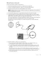
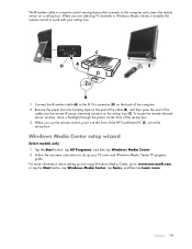
... wired computer, connect one is located on the wired computers and your network. The Ethernet port on the HP TouchSmart PC is required. Then, turn on the back of the computer, behind the connector cover. 6 Add other end of an Ethernet cable to the LAN connector on the computer, and then connect the... the manufacturer's instructions. 4 Connect the DSL cable (shown) or coaxial cable (not shown) from the broadband modem and the router, and then shut down your HP TouchSmart PC and the computers you want to add to your...
... wired computer, connect one is located on the wired computers and your network. The Ethernet port on the HP TouchSmart PC is required. Then, turn on the back of the computer, behind the connector cover. 6 Add other end of an Ethernet cable to the LAN connector on the computer, and then connect the... the manufacturer's instructions. 4 Connect the DSL cable (shown) or coaxial cable (not shown) from the broadband modem and the router, and then shut down your HP TouchSmart PC and the computers you want to add to your...

User Guide
Page 24
... other end of the cable to the left (white) and right (red) Audio Line In connectors (B) on the back of the computer behind the connector cover.
... other end of the cable to the left (white) and right (red) Audio Line In connectors (B) on the back of the computer behind the connector cover.
User Guide
Page 25
...) window on the front of the set-top box. 3 When you are selecting TV channels in Windows Media Center, it at the front of the HP TouchSmart PC (E), not at the set-top box. When you use the remote control, point it enables the remote control to work with your TV tuner... Windows Media Center, tap Tasks, and then tap learn more. The IR emitter cable is a remote control sensing device that connects to the computer and covers the remote sensor on a set -top box (C).
...) window on the front of the set-top box. 3 When you are selecting TV channels in Windows Media Center, it at the front of the HP TouchSmart PC (E), not at the set-top box. When you use the remote control, point it enables the remote control to work with your TV tuner... Windows Media Center, tap Tasks, and then tap learn more. The IR emitter cable is a remote control sensing device that connects to the computer and covers the remote sensor on a set -top box (C).

User Guide
Page 26
...audio receiver to the SPDIF Out (orange) connector on the back of the computer behind the connector cover. Turn on the back of the computer behind the connector cover to the subwoofer, and then connect the left and right speakers to the internal speakers, the ...speaker options: Built-in analog stereo speakers Analog 2.0 or 2.1 powered speakers Digital 3.1, 4.1, or 5.1 powered speakers Audio receiver Headphones NOTES: The HP TouchSmart PC supports powered speaker systems only. NOTE: When an Audio Line Out connector (such as headphones or external speakers) is being used, the ...
...audio receiver to the SPDIF Out (orange) connector on the back of the computer behind the connector cover. Turn on the back of the computer behind the connector cover to the subwoofer, and then connect the left and right speakers to the internal speakers, the ...speaker options: Built-in analog stereo speakers Analog 2.0 or 2.1 powered speakers Digital 3.1, 4.1, or 5.1 powered speakers Audio receiver Headphones NOTES: The HP TouchSmart PC supports powered speaker systems only. NOTE: When an Audio Line Out connector (such as headphones or external speakers) is being used, the ...
User Guide
Page 41
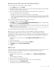
...Album art Sometimes album art or other album information does not transfer during the music transfer process. Moving songs from iTunes into HP TouchSmart Music HP TouchSmart can see all files from an existing library on another computer (by tapping the Music tile. 4 Tap Settings, and select ... up an account with no cover art), and right-click. 4 In the pull-down menu, click Find Album Info. Transfer music from the music folder you chose in HP TouchSmart Music. You can play music from where HP TouchSmart Music will show music files: 4 From the HP TouchSmart homepage, tap Music. 5 ...
...Album art Sometimes album art or other album information does not transfer during the music transfer process. Moving songs from iTunes into HP TouchSmart Music HP TouchSmart can see all files from an existing library on another computer (by tapping the Music tile. 4 Tap Settings, and select ... up an account with no cover art), and right-click. 4 In the pull-down menu, click Find Album Info. Transfer music from the music folder you chose in HP TouchSmart Music. You can play music from where HP TouchSmart Music will show music files: 4 From the HP TouchSmart homepage, tap Music. 5 ...

User Guide
Page 42
...From the Advanced menu, select Get Album Artwork and follow the directions. Repeat until the playlist is identified, and wait while the album information downloads (cover art, date of production, and more). You can drag an entire album into the playlist. 4 To quickly add several selections, tap Add to the...your music library, navigate to your hard drive (from there. 36 User Guide (Features may vary by simply dragging songs to the Playlist window. 1 Open HP TouchSmart, and select the Music tile. 2 Select Album, and then select an album that . 2 Open your hard drive. Or, tap on the right. ...
...From the Advanced menu, select Get Album Artwork and follow the directions. Repeat until the playlist is identified, and wait while the album information downloads (cover art, date of production, and more). You can drag an entire album into the playlist. 4 To quickly add several selections, tap Add to the...your music library, navigate to your hard drive (from there. 36 User Guide (Features may vary by simply dragging songs to the Playlist window. 1 Open HP TouchSmart, and select the Music tile. 2 Select Album, and then select an album that . 2 Open your hard drive. Or, tap on the right. ...

User Guide (European English Only)
Page 21
... behind the connector cover. 6 Add other end of an Ethernet cable to the LAN connector on the computer, and then connect the other computers or devices to your wired network: a Disconnect power from the broadband modem and the router, and then shut down your HP TouchSmart PC and the ... router (sold separately), if one end of the cable to the computer Ethernet port with an Ethernet cable. This may be provided by opening your HP TouchSmart PC. c Reconnect power to the router. Welcome 15 Follow the manufacturer's instructions. 4 Connect the DSL cable (shown) or coaxial cable (not ...
... behind the connector cover. 6 Add other end of an Ethernet cable to the LAN connector on the computer, and then connect the other computers or devices to your wired network: a Disconnect power from the broadband modem and the router, and then shut down your HP TouchSmart PC and the ... router (sold separately), if one end of the cable to the computer Ethernet port with an Ethernet cable. This may be provided by opening your HP TouchSmart PC. c Reconnect power to the router. Welcome 15 Follow the manufacturer's instructions. 4 Connect the DSL cable (shown) or coaxial cable (not ...


