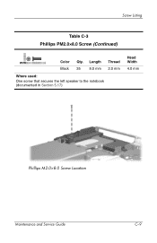
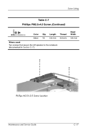
HP Pavilion zd8000 Notebook PC - Maintenance and Service Guide
Page 12
...1.1- Audio-out (headphone) jack (2) Connect optional headphones or powered stereo speakers. The type of optical drive, such as a television or VCR. Left-Side Components Item 1 2 3 4 5 Table 1-3 Left-Side Components Component Function Exhaust vent Provides airflow to block airflow. Also connects... do not obstruct vents. Optical drive Supports an optical disc. Product Description The external components on the left side of the notebook are shown below and described in (microphone) jack Connects an optional monaural microphone. or 2.0-compliant USB device. Audio...
HP Pavilion zd8000 Notebook PC - Maintenance and Service Guide
Page 53
Illustrated Parts Catalog Table 3-1 Spare Parts: Notebook Major Components (Continued) Item 7 8 9 10 11 12 13 14 15 16a ...(3.4-GHz) Intel Pentium 4 540 (3.2-GHz) Intel Pentium 4 530 (3.0-GHz) Intel Pentium 4 520 (2.8-GHz) Heat sink module (includes left fan and thermal paste) Modem board Base enclosure middle fan Base enclosure right fan Optical drives (include bezel) Dual Format, Double Layer...Scribe 8X DVD±RW/R and CD-RW Combo Drive 24X DVD/CD-RW Combo Drive Base enclosure Speakers Left Right Spare Part Number 374711-001 374709-001 374707-001 374761-001 377213-001 374718-001 374717-001 ...
HP Pavilion zd8000 Notebook PC - Maintenance and Service Guide
Page 68
... Dual Tuner Cable Kit Dual Tuner Miscellaneous Cable Kit Dual Tuner Plastic Stand Speakers, left and right 4200-rpm, 40-GB hard drive, includes frame and connector AC adapters, 135 watt, 2-wire plug-for use only on notebook models with Intel Pentium 4 530 (3.0-GHz) and Intel Pentium 4 520 ...(2.8-GHz) processors LED board 5400-rpm, 100-GB hard drive, includes frame and connector Switch cover for use with notebook models without wireless Base enclosure right fan Base enclosure middle fan Dual Format, Double Layer 8X Dual Format, Light Scribe 3-20 Maintenance and Service...
HP Pavilion zd8000 Notebook PC - Maintenance and Service Guide
Page 80
Removal and Replacement Procedures Disassembly Sequence Chart (Continued) Section 5.9 5.10 5.11 5.12 5.13 5.14 5.15 5.16 Description LED board Keyboard Display assembly Top cover Infrared board Audio/USB board Bluetooth board System board 5.17 Speakers 5.18 Digital drive board 5.19 Base enclosure fans 5.20 Modem board 5.21 Heat sink module 5.22 Processor # of Screws Removed 1 2 4 20 1 1 0 2 screw locks 7 screws 2 on left speaker 1 on right speaker 2 2 on left fan 4 on right fan 1 4 0 5-4 Maintenance and Service Guide
HP Pavilion zd8000 Notebook PC - Maintenance and Service Guide
Page 118
Disconnect the fan cable from the system board: 1 Left speaker cable 2 Front panel LED board cable 3 Digital drive board cable 4 Right speaker cable 5 Audio/USB board cable Disconnecting the System Board Cables, Part 1 6. Disconnecting the System Board Cables, Part 2 5-42 Maintenance and Service Guide Disconnect the following cables from the system board. Removal and Replacement Procedures 5.
HP Pavilion zd8000 Notebook PC - Maintenance and Service Guide
Page 121
... cover (refer to Section 5.7) d. Mini PCI compartment cover (refer to Section 5.12) h. Keyboard (refer to Section 5.11) g. 5.17 Speakers Removal and Replacement Procedures Spare Part Number Information Left and right speakers 378521-001 1. Position the notebook with the rear panel toward you. Display assembly (refer to Section 5.10) f. System board (refer to Section 5.8) e. Switch...
HP Pavilion zd8000 Notebook PC - Maintenance and Service Guide
Page 122
Removing the Left Speaker 5-46 Maintenance and Service Guide Remove the left speaker to the base enclosure. 4. Removal and Replacement Procedures 3. Remove the two PM2.0×4.0 1 screws that secure the left speaker 2.
HP Pavilion zd8000 Notebook PC - Maintenance and Service Guide
Page 171
Length Thread Black 35 8.0 mm 2.0 mm Where used: One screw that secures the left speaker to the notebook (documented in Section 5.17) Head Width 4.0 mm Phillips M2.0×8.0 Screw Location Maintenance and Service Guide C-9 Screw Listing Table C-3 Phillips PM2.0×8.0 Screw (Continued) mm Color Qty.
HP Pavilion zd8000 Notebook PC - Maintenance and Service Guide
Page 179
Length Thread Silver 10 4.0 mm 2.0 mm Where used: Two screws that secure the left speaker to the notebook (documented in Section 5.17) Head Width 4.0 mm Phillips M2.0×3.0 Screw Location Maintenance and Service Guide C-17 Screw Listing Table C-7 Phillips PM2.0×4.0 Screw (Continued) mm Color Qty.
HP Pavilion zd8000 Notebook PC - Maintenance and Service Guide
Page 188
... number 3-11, 3-19 screw listing C-1 security cable slot 1-9 serial number 3-1, 5-2 service considerations 4-2 speakers location 1-5 removal 5-45 spare part number 3-5, 3-20, 5-45 specifications battery pack 6-7 display 6-3, ...Combo Drive 6-10 hard drive 6-5, 6-6 I/O addresses 6-15 interrupts 6-13 memory map 6-18 notebook 6-1 static shielding materials 4-8 S-Video-out jack location 1-9 pin assignments A-2 switch cover removal... part number 3-3, 3-18, 5-30 TouchPad 1-15 TouchPad button 1-15 TouchPad left/right buttons 1-15 TouchPad light 1-15 TouchPad scroll zone 1-15 transporting precautions ...
Getting Started - Enhanced for Accessibility
Page 49
... a combination CD-ROM/DVD-ROM, varies by model. or 2.0-compliant USB device. Also connects the audio function of optical drive, such as a television or VCR. Notebook Tour Left-Side Components Connectors, Jacks and Components Component 1 USB port 2 Audio-in (microphone) jack 3 Audio-out (headphone) jack 4 Optical drive* Description Connects an optional 1.1- Connects...
Getting Started - Enhanced for Accessibility
Page 65
...preferences 2-1 setting up hardware 1-1 setting up software 2-1 slots Digital Media 4-13 ExpressCard 4-13 PC Card 4-13 security cable 4-9 SmartMedia card 4-13 software restoration 4-21 software setup 2-1 speakers 4-8 Standby power/standby light 4-8 resuming from 4-5 support, user 4-21 surge protection 3-6 ... label 4-20 troubleshooting 4-21 locked system 3-8, 4-5 notebook does not turn on 1-12 Troubleshooting guide 4-21 turning off notebook 3-8 turning on notebook 1-11 U USB ports 4-9, 4-11, 4-14 user accounts 2-9 V vents bottom 4-16 left-side 4-12 rear 4-10 virus protection 3-2 volume ...
Hardware Software Guide
Page 19
Also connects the audio function of optical drive, such as a television or VCR. Connects an optional monaural microphone. Connects optional headphones or powered stereo speakers. Hardware Left-Side Components Connectors, Jacks and Components Component 1 USB port 2 Audio-in (microphone) jack 3 Audio-out (headphone) jack 4 Optical drive* Description Connects an optional 1.1- Supports an ...
Hardware Software Guide
Page 72
... the Microphone Jack When connecting a microphone to 32-ohm headphones for best sound quality. ❏ The internal speakers are disabled. 4-4 Hardware and Software Guide The headphone jack is recommended. ■ If you connect a stereo microphone, left channel sound will record on headphones or a headset. Ä CAUTION: To prevent possible damage to an...