Installation Guide
Page 4
... use or reliability of its software on equipment that is subject to your HP Sales and Service Office or authorized dealer. © Copyright 2009-2010 Hewlett-Packard Development Company, L.P. Publication Number 5992-3084 March 2010 Applicable Products HP ProCurve 2910al-24G Switch HP ProCurve 2910al-48G Switch HP ProCurve 2910al-24G-PoE+ Switch HP ProCurve 2910al-48G-PoE+ Switch HP ProCurve 2-Port 10-GbE CX4 al Module HP ProCurve 2-Port 10-GbE SFP+ al Module HP ProCurve 10-GbE al Interconnect Kit HP ProCurve 620 Redundant and External Power Supply HP ProCurve...
... use or reliability of its software on equipment that is subject to your HP Sales and Service Office or authorized dealer. © Copyright 2009-2010 Hewlett-Packard Development Company, L.P. Publication Number 5992-3084 March 2010 Applicable Products HP ProCurve 2910al-24G Switch HP ProCurve 2910al-48G Switch HP ProCurve 2910al-24G-PoE+ Switch HP ProCurve 2910al-48G-PoE+ Switch HP ProCurve 2-Port 10-GbE CX4 al Module HP ProCurve 2-Port 10-GbE SFP+ al Module HP ProCurve 10-GbE al Interconnect Kit HP ProCurve 620 Redundant and External Power Supply HP ProCurve...

Installation Guide
Page 6
...the HP ProCurve 630 RPS/EPS (J9443A) 2-22 HP ProCurve 630 RPS/EPS Connectivity 2-24 9. (Optional) Connect a Console to Go From Here 3-4 To Recover from a Lost Manager Password 3-4 Using the IP Address for Remote Switch Management 3-5 Starting a Telnet Session 3-5 Starting a Web Browser Session 3-5 iv Connect the Network Cables 2-27 Using the RJ-45 Connectors 2-27 Connecting Cables to mini-GBICs 2-27 Connecting a fiber cable 2-28 Connecting a copper cable 2-28 Sample Network Topologies 2-29 3 Getting Started With Switch Configuration Recommended Minimal Configuration 3-1 Using the...
...the HP ProCurve 630 RPS/EPS (J9443A) 2-22 HP ProCurve 630 RPS/EPS Connectivity 2-24 9. (Optional) Connect a Console to Go From Here 3-4 To Recover from a Lost Manager Password 3-4 Using the IP Address for Remote Switch Management 3-5 Starting a Telnet Session 3-5 Starting a Web Browser Session 3-5 iv Connect the Network Cables 2-27 Using the RJ-45 Connectors 2-27 Connecting Cables to mini-GBICs 2-27 Connecting a fiber cable 2-28 Connecting a copper cable 2-28 Sample Network Topologies 2-29 3 Getting Started With Switch Configuration Recommended Minimal Configuration 3-1 Using the...

Installation Guide
Page 7
... with the LEDs 4-4 Proactive Networking 4-8 Hardware Diagnostic Tests 4-9 Testing the Switch by Resetting It 4-9 Checking the Switch LEDs 4-9 Checking Console Messages 4-9 Testing Twisted-Pair Cabling 4-10 Testing Switch-to-Device Network Communications 4-10 Testing End-to-End Network Communications 4-10 Restoring the Factory Default Configuration 4-11 Downloading New Switch Software 4-12 HP Customer Support Services 4-12 Before Calling Support 4-12 A Switch Specifications Physical A-1 Electrical A-1 Environmental A-1 Acoustic A-2 Safety A-2 B Module Specifications Physical...
... with the LEDs 4-4 Proactive Networking 4-8 Hardware Diagnostic Tests 4-9 Testing the Switch by Resetting It 4-9 Checking the Switch LEDs 4-9 Checking Console Messages 4-9 Testing Twisted-Pair Cabling 4-10 Testing Switch-to-Device Network Communications 4-10 Testing End-to-End Network Communications 4-10 Restoring the Factory Default Configuration 4-11 Downloading New Switch Software 4-12 HP Customer Support Services 4-12 Before Calling Support 4-12 A Switch Specifications Physical A-1 Electrical A-1 Environmental A-1 Acoustic A-2 Safety A-2 B Module Specifications Physical...

Installation Guide
Page 9
...24T Link 22S Mode 24S HP ProCurve 2910al-48G-PoE+ Switch (J9148A) ! The 2910al switches also support Redundant Power Supply and Power over Ethernet technologies. 1 Introducing the Switch Introducing the Switch Power Fault Locator Console ProCurve Switch 2910bl-24G J9145A Mdl * Spd mode: RPS Status of the Back off = 10 Mbps 2 flash = 100 Mbps Status Tmp LED Mode Fan Act FDx Spd * on = 1 Gbps 3 flash = 10 Gbps Fan PoE Test Usr Reset Clear Auxiliary Port HP ProCurve 2910al-24G-PoE+ Switch (J9146A) PoE+ Integrated 10/100/1000Base-T Ports (1 - 24T) — Ports are Auto-MDIX...
...24T Link 22S Mode 24S HP ProCurve 2910al-48G-PoE+ Switch (J9148A) ! The 2910al switches also support Redundant Power Supply and Power over Ethernet technologies. 1 Introducing the Switch Introducing the Switch Power Fault Locator Console ProCurve Switch 2910bl-24G J9145A Mdl * Spd mode: RPS Status of the Back off = 10 Mbps 2 flash = 100 Mbps Status Tmp LED Mode Fan Act FDx Spd * on = 1 Gbps 3 flash = 10 Gbps Fan PoE Test Usr Reset Clear Auxiliary Port HP ProCurve 2910al-24G-PoE+ Switch (J9146A) PoE+ Integrated 10/100/1000Base-T Ports (1 - 24T) — Ports are Auto-MDIX...

Installation Guide
Page 11
... mini-GBIC (SFP) connectivity. The mini-GBIC ports do not support connections to hubs, other switches, or routers. The 620 does not provide 54 V for PoE+, only 50 V for EPS. For a list of 15. This feature is on the ProCurve Web site at www.hp.com/go /procurve/manuals. HP ProCurve Redundant/External Power Supplies (RPS/EPS) can build a switched network infrastructure by connecting the switch to the 620 for PoE, and the 2910al Switches do not support PoE.
... mini-GBIC (SFP) connectivity. The mini-GBIC ports do not support connections to hubs, other switches, or routers. The 620 does not provide 54 V for PoE+, only 50 V for EPS. For a list of 15. This feature is on the ProCurve Web site at www.hp.com/go /procurve/manuals. HP ProCurve Redundant/External Power Supplies (RPS/EPS) can build a switched network infrastructure by connecting the switch to the 620 for PoE, and the 2910al Switches do not support PoE.
Installation Guide
Page 13
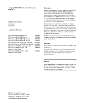
... 23T Link 21S Mode 23S Link 2 Mode 4 6 8 10 12 Link 14 Mode 16 18 20 22T 24T Link 22S Mode 24S ! Figure 1-4. ProCurve 2910al-48G-PoE+ Switch 1-5 Use only one (T or S) for each Port * ProCurve Switch Mdl EPS RPS Status of the unit. HP ProCurve 2910al-24G-PoE+ Switch Dual-personality ports (1000Base-T or mini-GBIC) Power, Fault, and locator LEDs PoE, Temp, Fan, and Test Status LEDs Module, EPS, and RPS Status LEDs Switch port LEDs ! Use only one (T or S) for each Port Console port Port LED Mode select button and indicator LEDs Reset and Clear buttons...
... 23T Link 21S Mode 23S Link 2 Mode 4 6 8 10 12 Link 14 Mode 16 18 20 22T 24T Link 22S Mode 24S ! Figure 1-4. ProCurve 2910al-48G-PoE+ Switch 1-5 Use only one (T or S) for each Port * ProCurve Switch Mdl EPS RPS Status of the unit. HP ProCurve 2910al-24G-PoE+ Switch Dual-personality ports (1000Base-T or mini-GBIC) Power, Fault, and locator LEDs PoE, Temp, Fan, and Test Status LEDs Module, EPS, and RPS Status LEDs Switch port LEDs ! Use only one (T or S) for each Port Console port Port LED Mode select button and indicator LEDs Reset and Clear buttons...

Installation Guide
Page 14
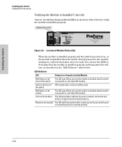
... modules. Switch LEDs Power (green) Fault (orange) 1-6 LEDs Table 1-2. All these ports have the "Auto MDIX" feature, which means you can use either straight-through either the 10/100/1000Base-T RJ-45 connector, or install a supported ProCurve miniGBIC (SFP) for more information. A fault has occurred on or reset, at the beginning of the Switch Network Ports ■ 24 or 48 auto-sensing 10/100/1000Base-T ports. See chapter 4, "Troubleshooting" for fiber-optic connections...
... modules. Switch LEDs Power (green) Fault (orange) 1-6 LEDs Table 1-2. All these ports have the "Auto MDIX" feature, which means you can use either straight-through either the 10/100/1000Base-T RJ-45 connector, or install a supported ProCurve miniGBIC (SFP) for more information. A fault has occurred on or reset, at the beginning of the Switch Network Ports ■ 24 or 48 auto-sensing 10/100/1000Base-T ports. See chapter 4, "Troubleshooting" for fiber-optic connections...

Installation Guide
Page 15
...). Link and Mode) LED Mode View (green LEDs) Mdl (Module Status, green) State On Flashing Off Off On green Flashing orange1 Link Mode Act FDx Spd PoE Usr On Flashing Off Meaning The Locator LED is disabled for a specified number of the Switch Switch LEDs Locator (Blue) Test (green/orange) Port LEDs (green/orange - The default view is 30 minutes. The switch is Flashing1 (orange) simultaneously with the Fault LED, the corresponding port has failed its self test. Press the button to locate a specific chassis...
...). Link and Mode) LED Mode View (green LEDs) Mdl (Module Status, green) State On Flashing Off Off On green Flashing orange1 Link Mode Act FDx Spd PoE Usr On Flashing Off Meaning The Locator LED is disabled for a specified number of the Switch Switch LEDs Locator (Blue) Test (green/orange) Port LEDs (green/orange - The default view is 30 minutes. The switch is Flashing1 (orange) simultaneously with the Fault LED, the corresponding port has failed its self test. Press the button to locate a specific chassis...

Installation Guide
Page 16
.... LED Mode Select Button and Indicator LEDs The operation of the Mode LED is controlled by the LED Mode indicator LEDs near the button. The switch has finished processing the USB command file successfully. RPS is not connected or is indicated by the LED Mode select button, and the current setting is not powered on /off only during the boot process. Introducing the Switch Introducing the Switch Front of the unit's fans has failed. If any port...
.... LED Mode Select Button and Indicator LEDs The operation of the Mode LED is controlled by the LED Mode indicator LEDs near the button. The switch has finished processing the USB command file successfully. RPS is not connected or is indicated by the LED Mode select button, and the current setting is not powered on /off only during the boot process. Introducing the Switch Introducing the Switch Front of the unit's fans has failed. If any port...

Installation Guide
Page 17
... PoE mode, the Link LED indicates the PoE configuration for the port: • On if PoE is enabled on the port • Off if PoE is lit, the port has a link. HP ProCurve 2910al-48G Switch Expansion Module LEDs Port LEDs Link and Mode Power Fault Locator Console ProCurve Switch 2910bl-48G-PoE J9148A PoE+ Mdl EPS RPS Status of the Back Link 1 Mode 3 5 Status Tmp LED Mode Fan Test Act FDx Spd * Usr Reset Clear Link 2 Mode 4 6 *Spd mode: 7 8 off=10 Mbps, 9 10 2 flash=100 Mbps, on=1 Gbps, 3 flash=10 Gbps 11 Link...
... PoE mode, the Link LED indicates the PoE configuration for the port: • On if PoE is enabled on the port • Off if PoE is lit, the port has a link. HP ProCurve 2910al-48G Switch Expansion Module LEDs Port LEDs Link and Mode Power Fault Locator Console ProCurve Switch 2910bl-48G-PoE J9148A PoE+ Mdl EPS RPS Status of the Back Link 1 Mode 3 5 Status Tmp LED Mode Fan Test Act FDx Spd * Usr Reset Clear Link 2 Mode 4 6 *Spd mode: 7 8 off=10 Mbps, 9 10 2 flash=100 Mbps, on=1 Gbps, 3 flash=10 Gbps 11 Link...
Installation Guide
Page 36
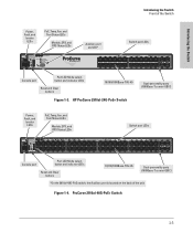
... soon as the module is installed and the switch is powered on , and stays ON steadily. LED Behavior LED Display for a Properly Installed Module Mdl Status on the front of Module Status LEDs When the module is installed properly and the switch is powered on = 1 Gbps 3 flash = 10 Gbps Fan PoE Test Usr Reset Clear Auxiliary Port Figure 2-8. Module Status LED Power Fault Locator Console ProCurve Switch 2910bl-24G-PoE Mdl EPS RPS Status of the Back J9146A PoE+ * Spd mode: Status PoE LED Tmp Mode Act FDx Spd...
... soon as the module is installed and the switch is powered on , and stays ON steadily. LED Behavior LED Display for a Properly Installed Module Mdl Status on the front of Module Status LEDs When the module is installed properly and the switch is powered on = 1 Gbps 3 flash = 10 Gbps Fan PoE Test Usr Reset Clear Auxiliary Port Figure 2-8. Module Status LED Power Fault Locator Console ProCurve Switch 2910bl-24G-PoE Mdl EPS RPS Status of the Back J9146A PoE+ * Spd mode: Status PoE LED Tmp Mode Act FDx Spd...
Installation Guide
Page 50
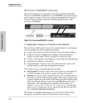
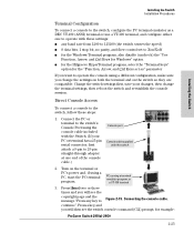
... to use console interface for connecting a PC or VT-100 terminal, to the RPS and EPS ports on the HP ProCurve Web site at www.hp.com/go/procurve/manuals. The Switch can simultaneously support one out-of -band console access or through the Console Port and one ProCurve switch. Installing the Switch 2910al Switch HP ProCurve 630 RPS/EPS Figure 2-18. Installing the Switch Installation Procedures HP ProCurve 630 RPS/EPS Connectivity This section shows the recommended connection topology using Telnet from the console, web browser interface, and network management...
... to use console interface for connecting a PC or VT-100 terminal, to the RPS and EPS ports on the HP ProCurve Web site at www.hp.com/go/procurve/manuals. The Switch can simultaneously support one out-of -band console access or through the Console Port and one ProCurve switch. Installing the Switch 2910al Switch HP ProCurve 630 RPS/EPS Figure 2-18. Installing the Switch Installation Procedures HP ProCurve 630 RPS/EPS Connectivity This section shows the recommended connection topology using Telnet from the console, web browser interface, and network management...
Installation Guide
Page 51
... for example: ProCurve Switch 2910al-24G# 2-25 Turn on the switch so they are compatible. Press a key, and you will then see the copyright page and the message "Press any baud rate from 1200 to 115200 (the switch senses the speed) ■ 8 data bits, 1 stop bit, no parity, and flow control set to Figure 2-19. Press [Enter] two or three times and you will see the switch console command (CLI...
... for example: ProCurve Switch 2910al-24G# 2-25 Turn on the switch so they are compatible. Press a key, and you will then see the copyright page and the message "Press any baud rate from 1200 to 115200 (the switch senses the speed) ■ 8 data bits, 1 stop bit, no parity, and flow control set to Figure 2-19. Press [Enter] two or three times and you will see the switch console command (CLI...
Installation Guide
Page 60
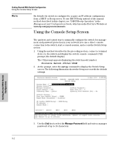
... section, connect a terminal device to the switch and display the switch console command (CLI) prompt (the default display). Using the method described in the Management and Configuration Guide, which is on the ProCurve Website at www.hp.com/go/procurve/manuals. Getting Started With Switch Configuration Using the Console Setup Screen Note By default, the switch is to use DHCP/Bootp instead of up to 16 characters. 3-2 The CLI prompt appears displaying the switch model number: ProCurve Switch 2910al-48G# 2. Using the Console Setup Screen The...
... section, connect a terminal device to the switch and display the switch console command (CLI) prompt (the default display). Using the method described in the Management and Configuration Guide, which is on the ProCurve Website at www.hp.com/go/procurve/manuals. Getting Started With Switch Configuration Using the Console Setup Screen Note By default, the switch is to use DHCP/Bootp instead of up to 16 characters. 3-2 The CLI prompt appears displaying the switch model number: ProCurve Switch 2910al-48G# 2. Using the Console Setup Screen The...
Installation Guide
Page 71
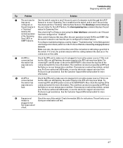
... have failed. Also check the log files of the connected switch for more information. The show lacp command displays the port may configured, or have been put into a "blocking" state by the normal operation of the switch. Also check the Port Status screen using the show spanning-tree command displays the port a "blocking" status for these features. For software troubleshooting tips, see if Spanning Tree is not, the problem may be with the LEDs Tip Problem Solution...
... have failed. Also check the log files of the connected switch for more information. The show lacp command displays the port may configured, or have been put into a "blocking" state by the normal operation of the switch. Also check the Port Status screen using the show spanning-tree command displays the port a "blocking" status for these features. For software troubleshooting tips, see if Spanning Tree is not, the problem may be with the LEDs Tip Problem Solution...

Installation Guide
Page 75
... Website at www.hp.com/go/procurve/manuals. Then, after the reset and resolution of the original problem, you have made from the console command prompt. 4-11 Troubleshooting This includes, for a reason other than configuration problems, you should save and restore processes, you are restoring the factory default settings for example, configuration of VLANs, Spanning Tree, trunks, and stacking. To restore the factory default configuration using the console, execute the erase startup-config command from the factory default settings. Returning the configuration of these steps...
... Website at www.hp.com/go/procurve/manuals. Then, after the reset and resolution of the original problem, you have made from the console command prompt. 4-11 Troubleshooting This includes, for a reason other than configuration problems, you should save and restore processes, you are restoring the factory default settings for example, configuration of VLANs, Spanning Tree, trunks, and stacking. To restore the factory default configuration using the console, execute the erase startup-config command from the factory default settings. Returning the configuration of these steps...

Installation Guide
Page 110
... default configuration, restoring ... 1-10, 4-11 Fan Status LED ... 1-8, 2-20, 2-23 fan Status LED ... 1-8 Fault LED ... 2-20, 2-23 behavior during troubleshooting ... 4-9 displaying the CLI prompt ... 2-25 features ... 2-24 how to connect in -band access ... 2-24 diagnostic tests ... 4-9 checking the console messages ... 4-9 checking the LEDs ... 4-9 end-to connect out-of mini-GBICs ... 2-16 G gigabit edge switch sample topology ... 2-29 H horizontal surface mounting switch on ... 2-13 HP Auto-MDIX feature description ... C-3 1000Base-T ... A-1, B-1 EPS input port ... 1-13 expansion module...
... default configuration, restoring ... 1-10, 4-11 Fan Status LED ... 1-8, 2-20, 2-23 fan Status LED ... 1-8 Fault LED ... 2-20, 2-23 behavior during troubleshooting ... 4-9 displaying the CLI prompt ... 2-25 features ... 2-24 how to connect in -band access ... 2-24 diagnostic tests ... 4-9 checking the console messages ... 4-9 checking the LEDs ... 4-9 end-to connect out-of mini-GBICs ... 2-16 G gigabit edge switch sample topology ... 2-29 H horizontal surface mounting switch on ... 2-13 HP Auto-MDIX feature description ... C-3 1000Base-T ... A-1, B-1 EPS input port ... 1-13 expansion module...

Installation Guide
Page 111
... 2-1 installation al module ... 2-8 connecting the switch to a power source ... 2-18 horizontal surface mounting ... 2-13 location considerations ... 2-5 network cable requirements ... 2-5 precautions ... 2-3 rack or cabinet mounting ... 2-11 site preparation ... 2-5 summary of steps ... 2-4 transceiver ... 2-14 IP address configuring ... 3-3 L LEDs Act ... 1-7, 1-9 behavior during self test ... 2-7 checking during troubleshooting ... 4-9 descriptions of -band console access ... 3-5 P parts, included with the switch ... 2-1 password configuring ... 3-2 passwords deleting with the Clear button...
... 2-1 installation al module ... 2-8 connecting the switch to a power source ... 2-18 horizontal surface mounting ... 2-13 location considerations ... 2-5 network cable requirements ... 2-5 precautions ... 2-3 rack or cabinet mounting ... 2-11 site preparation ... 2-5 summary of steps ... 2-4 transceiver ... 2-14 IP address configuring ... 3-3 L LEDs Act ... 1-7, 1-9 behavior during self test ... 2-7 checking during troubleshooting ... 4-9 descriptions of -band console access ... 3-5 P parts, included with the switch ... 2-1 password configuring ... 3-2 passwords deleting with the Clear button...

Installation Guide
Page 112
...... 1-3 port configuration checking when troubleshooting ... 4-3 Port LED View indicator LEDs ... 1-8 select button ... 1-8 selecting the display ... 1-8 port LEDs description ... 1-7, 2-20, 2-23 Link ... 1-7, 1-11 normal operation ... 2-7 ports 10/100Base-TX, location on switch ... 1-4 Spd LEDs ... 1-7 specifications cabling ... E-1 regulatory statements ... A-1, B-1 physical ... passwords, deleting ... 1-10 physical specifications, switch ... C-6 network connections ... 2-27 power connector ... 1-13 power cords ... 2-2 Power LED ... 1-6, 2-20, 2-23 behavior during factory default reset...
...... 1-3 port configuration checking when troubleshooting ... 4-3 Port LED View indicator LEDs ... 1-8 select button ... 1-8 selecting the display ... 1-8 port LEDs description ... 1-7, 2-20, 2-23 Link ... 1-7, 1-11 normal operation ... 2-7 ports 10/100Base-TX, location on switch ... 1-4 Spd LEDs ... 1-7 specifications cabling ... E-1 regulatory statements ... A-1, B-1 physical ... passwords, deleting ... 1-10 physical specifications, switch ... C-6 network connections ... 2-27 power connector ... 1-13 power cords ... 2-2 Power LED ... 1-6, 2-20, 2-23 behavior during factory default reset...

Installation Guide
Page 113
... port configuration ... 4-3 checking the console messages ... 4-9 checking the LEDs ... 4-9 common network problems ... 4-1 connecting to fixed full-duplex devices ... 4-1 diagnostic tests ... 4-9 effects of improper topology ... 4-2 effects of non-standard cables ... 4-2 link test ... 4-10 Ping test ... 4-10 Proactive Network tools ... 4-8 restoring factory default configuration ... 4-11 testing connections to other devices ... 4-10 testing end-to a power source ... 2-18 description ... 1-1 downloading new software ... 4-12 electrical specifications ... C-7, C-9 switch-to -switch or hub...
... port configuration ... 4-3 checking the console messages ... 4-9 checking the LEDs ... 4-9 common network problems ... 4-1 connecting to fixed full-duplex devices ... 4-1 diagnostic tests ... 4-9 effects of improper topology ... 4-2 effects of non-standard cables ... 4-2 link test ... 4-10 Ping test ... 4-10 Proactive Network tools ... 4-8 restoring factory default configuration ... 4-11 testing connections to other devices ... 4-10 testing end-to a power source ... 2-18 description ... 1-1 downloading new software ... 4-12 electrical specifications ... C-7, C-9 switch-to -switch or hub...


