
English Manual
Page 2
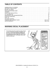
... manual and request a free replacement decal. HEALTHRIDER is missing or illegible, see the front cover of ICON IP, Inc. 2 Apply the decal in the location shown. TABLE OF CONTENTS WARNING DECAL PLACEMENT 2 IMPORTANT PRECAUTIONS 3 BEFORE YOU BEGIN 6 PART IDENTIFICATION CHART 7 ASSEMBLY 8 HOW TO USE THE ELLIPTICAL 18 FCC INFORMATION 26 MAINTENANCE AND TROUBLESHOOTING...
... manual and request a free replacement decal. HEALTHRIDER is missing or illegible, see the front cover of ICON IP, Inc. 2 Apply the decal in the location shown. TABLE OF CONTENTS WARNING DECAL PLACEMENT 2 IMPORTANT PRECAUTIONS 3 BEFORE YOU BEGIN 6 PART IDENTIFICATION CHART 7 ASSEMBLY 8 HOW TO USE THE ELLIPTICAL 18 FCC INFORMATION 26 MAINTENANCE AND TROUBLESHOOTING...

English Manual
Page 7
Extra parts may be included. PART IDENTIFICATION CHART Use the drawings below each drawing is the quantity needed for assembly. The number in the hardware kit, check to identify the small parts needed for assembly. The number following the key number is the key number of the part, from the PART LIST near...
Extra parts may be included. PART IDENTIFICATION CHART Use the drawings below each drawing is the quantity needed for assembly. The number in the hardware kit, check to identify the small parts needed for assembly. The number following the key number is the key number of the part, from the PART LIST near...
English Manual
Page 8
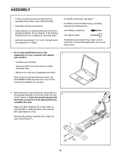
... you time if you ever need to contact Customer Care •• allows us to the included tool(s), assembly requires the following tools: one Phillips screwdriver one rubber mallet Assembly may be easier if you have a set of wrenches. Have the second person hold the Frame to the ... rear 2 of the Frame (1). To avoid damaging parts, do not have Internet access, call 1-800-445-2480. •• Assembly requires two persons. •• Place all assembly steps. •• Left parts are marked “"L”" or “"Left”" and right parts are marked “"R”"...
... you time if you ever need to contact Customer Care •• allows us to the included tool(s), assembly requires the following tools: one Phillips screwdriver one rubber mallet Assembly may be easier if you have a set of wrenches. Have the second person hold the Frame to the ... rear 2 of the Frame (1). To avoid damaging parts, do not have Internet access, call 1-800-445-2480. •• Assembly requires two persons. •• Place all assembly steps. •• Left parts are marked “"L”" or “"Left”" and right parts are marked “"R”"...
English Manual
Page 28
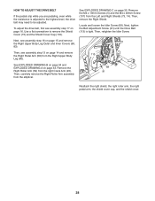
...remove the Right Upper Body Leg Outer and Inner Covers (69, 83). Remove the M4 x 19mm Screws (5) and the M4 x 48mm Screw (107) from the elliptical. 89 91 Reattach the right shield, the right roller arm, the right pedal arm, the shield cover cap, and the shield cover. 28 Next, tighten... Shield Cover Cap (118). Then, remove the Right Shield. Then, retighten the Idler Screw. Then, carefully remove the Right Roller Arm assembly from the Left and Right Shields (73, 74). Next, see assembly step 16 on page 33. See EXPLODED DRAWING C on page 16. To adjust the drive belt, first see...
...remove the Right Upper Body Leg Outer and Inner Covers (69, 83). Remove the M4 x 19mm Screws (5) and the M4 x 48mm Screw (107) from the elliptical. 89 91 Reattach the right shield, the right roller arm, the right pedal arm, the shield cover cap, and the shield cover. 28 Next, tighten... Shield Cover Cap (118). Then, remove the Right Shield. Then, retighten the Idler Screw. Then, carefully remove the Right Roller Arm assembly from the Left and Right Shields (73, 74). Next, see assembly step 16 on page 33. See EXPLODED DRAWING C on page 16. To adjust the drive belt, first see...

English Manual
Page 32
.... Key No. M4 x 19mm Self-tapping Screw Drive Belt M4 x 42mm Screw M4 x 30mm Screw Disc Ring Front Upright Cover Shield Cover Cap Power Adapter Assembly Tool Grease Packet User’'s Manual Note: Specifications are not illustrated. 32 Description Key No. Description 101 38 102 10 103 8 104 4 105 8 106 3 107...
.... Key No. M4 x 19mm Self-tapping Screw Drive Belt M4 x 42mm Screw M4 x 30mm Screw Disc Ring Front Upright Cover Shield Cover Cap Power Adapter Assembly Tool Grease Packet User’'s Manual Note: Specifications are not illustrated. 32 Description Key No. Description 101 38 102 10 103 8 104 4 105 8 106 3 107...

