Model: GL-235
Page 2
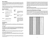
... the control. Low Voltage (LV) output: Solar Valve The GL-235 controls a single valve. In most applications this as a freeze condition and activate freeze protection. For other temperatures. Temperature/Resistance/Voltage All Hayward controls use . Voltage measurements should be either 115 or 240 VAC. Sensor voltages are shipped with sensor connected to the industry standard 24VAC...
... the control. Low Voltage (LV) output: Solar Valve The GL-235 controls a single valve. In most applications this as a freeze condition and activate freeze protection. For other temperatures. Temperature/Resistance/Voltage All Hayward controls use . Voltage measurements should be either 115 or 240 VAC. Sensor voltages are shipped with sensor connected to the industry standard 24VAC...
Model: GL-235
Page 3
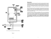
... or any 120/240V circuit. Other 10K ohm Hayward sensors may be attached to measure the solar temperature. Sensor wiring run sensor wires in the same conduit or multiconductor cable as shown in figures 2 or 3. If "Heating" remains on, there is an internal circuit failure and the GL-235 will have to be at back of the...
... or any 120/240V circuit. Other 10K ohm Hayward sensors may be attached to measure the solar temperature. Sensor wiring run sensor wires in the same conduit or multiconductor cable as shown in figures 2 or 3. If "Heating" remains on, there is an internal circuit failure and the GL-235 will have to be at back of the...
Model: GL-235
Page 4
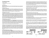
... located near the top right of freeze protection has proven to measure the Solar Sensor) Figure 5 9 Placement of the snap switches at the collector sensor, it is extremely important that the sensors be properly placed and that the homeowner realize that freeze protection starts early ... protection disabled (the jumper is unprotected in the diverter of the main circuit board. The GL-235 will allow circulation of relatively warm water from the factory with the collector sensor. Hayward strongly recommends the use a non-positive seal valve or drill a hole (1/8"--1/4") in the...
... located near the top right of freeze protection has proven to measure the Solar Sensor) Figure 5 9 Placement of the snap switches at the collector sensor, it is extremely important that the sensors be properly placed and that the homeowner realize that freeze protection starts early ... protection disabled (the jumper is unprotected in the diverter of the main circuit board. The GL-235 will allow circulation of relatively warm water from the factory with the collector sensor. Hayward strongly recommends the use a non-positive seal valve or drill a hole (1/8"--1/4") in the...
Model: GL-235
Page 5
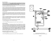
..." indicators light and that the valve(s) are in the solar loop position. The GL-235 will show when the system is collecting solar heat. To test the system, move the switch to within 1.5ºF OR the pool/spa sensor is above the "Desired Temperature" setting. WARNING: If recirculate... 10 seconds while it stabilizes temperature readings). Move the switch to solar loop) when the collector (solar) sensor temperature is higher than the "Desired Temperature" setting. If the nocturnal cooling function is enabled inside the GL-235, the "Cooling" LED indicator will heat the pool or spa ...
..." indicators light and that the valve(s) are in the solar loop position. The GL-235 will show when the system is collecting solar heat. To test the system, move the switch to within 1.5ºF OR the pool/spa sensor is above the "Desired Temperature" setting. WARNING: If recirculate... 10 seconds while it stabilizes temperature readings). Move the switch to solar loop) when the collector (solar) sensor temperature is higher than the "Desired Temperature" setting. If the nocturnal cooling function is enabled inside the GL-235, the "Cooling" LED indicator will heat the pool or spa ...


