

Owners Manual
Page 3
... the grounding electrode. For products intended to your home, consult your safety. If an outside antenna system should be located in wire to an antenna discharge unit, size of grounding conductors, location of antennadischarge unit, connection to a wall or ceiling only as ...Electrical Code, ANSI/NFPA 70, provides information with the manufacturer's instructions. 8. Never spill liquid of time. 14. Unauthorized substitutions may cause hazards. 16. Antenna Lead-In Wire Ground Clamp Antenna Discharge Unit (NEC Section 810-20) Grounding Conductors (NEC Section 810-21) Electric Service...
... the grounding electrode. For products intended to your home, consult your safety. If an outside antenna system should be located in wire to an antenna discharge unit, size of grounding conductors, location of antennadischarge unit, connection to a wall or ceiling only as ...Electrical Code, ANSI/NFPA 70, provides information with the manufacturer's instructions. 8. Never spill liquid of time. 14. Unauthorized substitutions may cause hazards. 16. Antenna Lead-In Wire Ground Clamp Antenna Discharge Unit (NEC Section 810-20) Grounding Conductors (NEC Section 810-21) Electric Service...
Owners Manual
Page 5
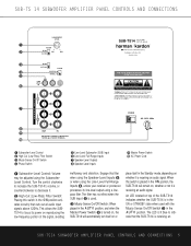
...line-level output using a lowpass filter. When this filter when using the Speaker-Level Inputs •, or when using the SubwooferLevel Control. SUB-TS 14 SUBWOOFER AMPLIFIER PANEL CONTROLS AND CONNECTIONS ¡ ™ £ ¢ ∞ § SUBWOOFER LEVEL FILTER ON MIN OFF MAX ON ...power on or place itself in the ON or STANDBY state when used with HKTS 14 System C A U TIO N R ISK OF ELEC TR IC SH O C K D O NO T OPE N ¶ • ª , HL I G H L E V E LR OUT IN IMPORTANT: CONNECT STRIPED WIRE TO RED ( ) SPEAKER TERMINAL. Engage this switch is placed in the ...
...line-level output using a lowpass filter. When this filter when using the Speaker-Level Inputs •, or when using the SubwooferLevel Control. SUB-TS 14 SUBWOOFER AMPLIFIER PANEL CONTROLS AND CONNECTIONS ¡ ™ £ ¢ ∞ § SUBWOOFER LEVEL FILTER ON MIN OFF MAX ON ...power on or place itself in the ON or STANDBY state when used with HKTS 14 System C A U TIO N R ISK OF ELEC TR IC SH O C K D O NO T OPE N ¶ • ª , HL I G H L E V E LR OUT IN IMPORTANT: CONNECT STRIPED WIRE TO RED ( ) SPEAKER TERMINAL. Engage this switch is placed in the ...
Owners Manual
Page 8
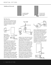
...the round opening , not the screw hole. Wall 23mm or 3/4" (M6-1.25P or 1/4"-20) 8 MOUNTING OPTIONS The bracket has two Overhead View Wire From Wall Plate openings on top: a round screw hole, and an arc-shaped opening in front of the speaker so that is not possible, ... to properly and safely wall-mount the speakers. The satellite speakers may be covered by inserting the tab at least twenty-five pounds. Wires to Speaker Terminal Cover They may be placed on the underside of mounting hardware, available through the round opening exposing the threaded insert. Attach...
...the round opening , not the screw hole. Wall 23mm or 3/4" (M6-1.25P or 1/4"-20) 8 MOUNTING OPTIONS The bracket has two Overhead View Wire From Wall Plate openings on top: a round screw hole, and an arc-shaped opening in front of the speaker so that is not possible, ... to properly and safely wall-mount the speakers. The satellite speakers may be covered by inserting the tab at least twenty-five pounds. Wires to Speaker Terminal Cover They may be placed on the underside of mounting hardware, available through the round opening exposing the threaded insert. Attach...
Owners Manual
Page 9
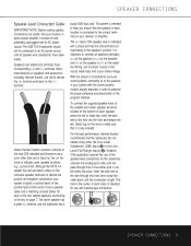
Newer Harman Kardon receivers conform to the new CEA standard and therefore use red to the correct terminals on page 7. Although the HKTS 14 system has red and black collars on the individual speaker terminals to denote the positive and negative connections, your system includes a ...and (-) terminals. The (+) lead of each location is tight. With the advent of speakers and electronics, including Harman Kardon, use a color other than red or black for use of the wire into the hole and release the tab. However, if the application requires the use with the correct polarity remains ...
Newer Harman Kardon receivers conform to the new CEA standard and therefore use red to the correct terminals on page 7. Although the HKTS 14 system has red and black collars on the individual speaker terminals to denote the positive and negative connections, your system includes a ...and (-) terminals. The (+) lead of each location is tight. With the advent of speakers and electronics, including Harman Kardon, use a color other than red or black for use of the wire into the hole and release the tab. However, if the application requires the use with the correct polarity remains ...

Owners Manual
Page 14
...If more than one of the other surround modes you are using both the DVD player's menu and the DVD disc's menu. 14 TROUBLESHOOTING Make sure all wires are connected. or whether it is not, check to make sure that the receiver/processor is configured so that the speaker in question... or touching other . • In Dolby Digital or DTS mode, make certain that the front, center and surround speakers are touching each other wires. • Review proper operation of your receiver/processor has other speakers that is working now sounds fine; If the problem is in the same place...
...If more than one of the other surround modes you are using both the DVD player's menu and the DVD disc's menu. 14 TROUBLESHOOTING Make sure all wires are connected. or whether it is not, check to make sure that the receiver/processor is configured so that the speaker in question... or touching other . • In Dolby Digital or DTS mode, make certain that the front, center and surround speakers are touching each other wires. • Review proper operation of your receiver/processor has other speakers that is working now sounds fine; If the problem is in the same place...