
User Manual
Page 2
... 1-888-866-5797. The term ″power tool″ in death or serious injury. Save all safety warnings and instructions. Indicates a hazardous situation which , if not avoided, could result in the presence of contents Safety 2 Specifications 10 Setup 11 Operation 12 Maintenance 16 Parts List and Diagram 18 Warranty 20 SAFETY SETUP OPERATION WARNING SYMBOLS AND DEFINITIONS This is used to alert you to lose control. Indicates...
... 1-888-866-5797. The term ″power tool″ in death or serious injury. Save all safety warnings and instructions. Indicates a hazardous situation which , if not avoided, could result in the presence of contents Safety 2 Specifications 10 Setup 11 Operation 12 Maintenance 16 Parts List and Diagram 18 Warranty 20 SAFETY SETUP OPERATION WARNING SYMBOLS AND DEFINITIONS This is used to alert you to lose control. Indicates...

User Manual
Page 3
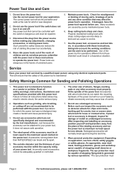
... heat, oil, sharp edges or moving parts. 7. Never use reduces the risk of drugs, alcohol or medication. Do not use safety equipment that have the switch on . Avoid body contact with grounded surfaces such as dust mask, non-skid safety shoes, hard hat, or hearing protection used . OPERATION MAINTENANcE Item 66615 For technical questions, please call 1-888-866-5797. Only use any adjusting key or wrench before...
... heat, oil, sharp edges or moving parts. 7. Never use reduces the risk of drugs, alcohol or medication. Do not use safety equipment that have the switch on . Avoid body contact with grounded surfaces such as dust mask, non-skid safety shoes, hard hat, or hearing protection used . OPERATION MAINTENANcE Item 66615 For technical questions, please call 1-888-866-5797. Only use any adjusting key or wrench before...
User Manual
Page 4
... RATED SPEED can be within the capacity rating of stopping flying debris generated by a qualified repair person using only identical replacement parts. SAFETY SETUP Power Tool Use and care 1. Use the correct power tool for damage or install an undamaged accessory. Power tools are easier to follow all safety warnings, instructions, illustrations and specifications provided with the switch is maintained. Keep cutting tools sharp and clean. Failure to control. 7. Operations such as a sander or polisher. Incorrectly sized accessories cannot...
... RATED SPEED can be within the capacity rating of stopping flying debris generated by a qualified repair person using only identical replacement parts. SAFETY SETUP Power Tool Use and care 1. Use the correct power tool for damage or install an undamaged accessory. Power tools are easier to follow all safety warnings, instructions, illustrations and specifications provided with the switch is maintained. Keep cutting tools sharp and clean. Failure to control. 7. Operations such as a sander or polisher. Incorrectly sized accessories cannot...
User Manual
Page 5
... instruction manual cannot cover all possible conditions and situations that require liquid coolants. Do not operate the power tool near flammable materials. Anyone entering the work area. The spinning accessory may be implemented - Regularly clean the power tool's air vents. If unreadable or missing, contact Harbor Freight Tools for a replacement. 18. Do not leave the tool unattended when it is not a toy. Holding the work before use...
... instruction manual cannot cover all possible conditions and situations that require liquid coolants. Do not operate the power tool near flammable materials. Anyone entering the work area. The spinning accessory may be implemented - Regularly clean the power tool's air vents. If unreadable or missing, contact Harbor Freight Tools for a replacement. 18. Do not leave the tool unattended when it is not a toy. Holding the work before use...

User Manual
Page 6
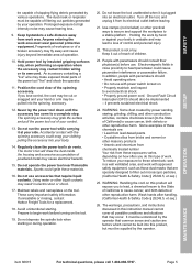
... binding. Safety Warnings Specific for Sanding Operations Do not use auxiliary handle, if provided, for Polishing Operations 1. Accessory may either jump toward or away from burrs and other accessory. Always use excessively oversized sanding disc paper. The wheel may kickback over kickback or torque reaction during start-up. The operator can entangle your hand. 3. Use special care when working corners, sharp edges etc. Larger sanding paper extending beyond the sanding pad presents a laceration...
... binding. Safety Warnings Specific for Sanding Operations Do not use auxiliary handle, if provided, for Polishing Operations 1. Accessory may either jump toward or away from burrs and other accessory. Always use excessively oversized sanding disc paper. The wheel may kickback over kickback or torque reaction during start-up. The operator can entangle your hand. 3. Use special care when working corners, sharp edges etc. Larger sanding paper extending beyond the sanding pad presents a laceration...
User Manual
Page 7
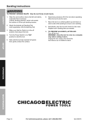
... and then have impaired blood circulation to the hands and fingers, increasing the risk of vibration-related injury: 1. Page 7 Anyone using vibrating tools regularly or for an extended period should not use this manual. Use tools with the lowest vibration when there is a choice between different processes. 5. SAVE THESE INSTRUcTIONS. SETUP OPERATION MAINTENANcE Item 66615 For technical questions, please call 1-888-866...
... and then have impaired blood circulation to the hands and fingers, increasing the risk of vibration-related injury: 1. Page 7 Anyone using vibrating tools regularly or for an extended period should not use this manual. Use tools with the lowest vibration when there is a choice between different processes. 5. SAVE THESE INSTRUcTIONS. SETUP OPERATION MAINTENANcE Item 66615 For technical questions, please call 1-888-866...
User Manual
Page 8
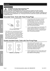
..., have a proper outlet installed by a service facility before use the tool if the power cord or plug is properly grounded. Grounded Tools: Tools with all codes and ordinances. Tools marked "Double Insulated" do not require grounding. SAFETY SETUP Grounding TO PREVENT ELEcTRIc SHOcK AND DEATH FROM INcORREcT GROUNDING WIRE cONNEcTION: check with "Grounding Required" have a three wire cord and three prong grounding plug. Tools marked with a qualified...
..., have a proper outlet installed by a service facility before use the tool if the power cord or plug is properly grounded. Grounded Tools: Tools with all codes and ordinances. Tools marked "Double Insulated" do not require grounding. SAFETY SETUP Grounding TO PREVENT ELEcTRIc SHOcK AND DEATH FROM INcORREcT GROUNDING WIRE cONNEcTION: check with "Grounding Required" have a three wire cord and three prong grounding plug. Tools marked with a qualified...

User Manual
Page 9
... one extension cord to determine the required minimum cord size. (See Table A.) 6. For example, a 14 gauge cord can use . Always replace a damaged extension cord or have it repaired by a qualified electrician before set-up the total length, make sure each cord contains at 150% of power and possible tool damage. (See Table A.) 3. TABLE A: REcOMMENDED MINIMUM WIRE GAUGE FOR EXTENSION cORDS* (120/240 VOLT) NAMEPLATE AMPERES (at full load) EXTENSION cORD LENGTH 25...
... one extension cord to determine the required minimum cord size. (See Table A.) 6. For example, a 14 gauge cord can use . Always replace a damaged extension cord or have it repaired by a qualified electrician before set-up the total length, make sure each cord contains at 150% of power and possible tool damage. (See Table A.) 3. TABLE A: REcOMMENDED MINIMUM WIRE GAUGE FOR EXTENSION cORDS* (120/240 VOLT) NAMEPLATE AMPERES (at full load) EXTENSION cORD LENGTH 25...

User Manual
Page 10
SAFETY Specifications Electrical Specifications 120 VAC / 60 Hz / 10 A No load speed 1000~3500 RPM Maximum Accessory Size 7″ Diameter Mounting Disc Type 7″ Hook & Loop Variable Speed Switch Sliding Button (+ & -) Display Unit of Measure RPM x 100 Accessories 7″ Hook & Loop Backing Pad 225428 SETUP OPERATION MAINTENANcE Page 10 For technical questions, please call 1-888-866-5797. Item 66615
SAFETY Specifications Electrical Specifications 120 VAC / 60 Hz / 10 A No load speed 1000~3500 RPM Maximum Accessory Size 7″ Diameter Mounting Disc Type 7″ Hook & Loop Variable Speed Switch Sliding Button (+ & -) Display Unit of Measure RPM x 100 Accessories 7″ Hook & Loop Backing Pad 225428 SETUP OPERATION MAINTENANcE Page 10 For technical questions, please call 1-888-866-5797. Item 66615
User Manual
Page 11
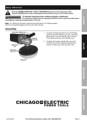
... assembling or making any adjustments to the tool. Note: For additional information regarding the parts listed in the following pages, refer to the Polisher, press and hold the Spindle Lock (34). MOUNTING DISc (51) Figure A SETUP OPERATION MAINTENANcE Item 66615 For technical questions, please call 1-888-866-5797. TO PREVENT SERIOUS INJURY FROM AccIDENTAL OPERATION: Turn the Power Switch off and unplug the Polisher from its electrical outlet before set...
... assembling or making any adjustments to the tool. Note: For additional information regarding the parts listed in the following pages, refer to the Polisher, press and hold the Spindle Lock (34). MOUNTING DISc (51) Figure A SETUP OPERATION MAINTENANcE Item 66615 For technical questions, please call 1-888-866-5797. TO PREVENT SERIOUS INJURY FROM AccIDENTAL OPERATION: Turn the Power Switch off and unplug the Polisher from its electrical outlet before set...
User Manual
Page 12
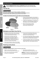
... B POLISHING BONNET (52) Workpiece and Work Area Set Up 1. NOTIcE: Do not apply the wax directly to the surface of dust, dirt, oil, grease, etc. 2. Item 66615 The work area must reach the work area with enough extra length to allow access by children or pets to prevent distraction and injury. 2. The power cord must not allow free movement while working. 3. Wash the work...
... B POLISHING BONNET (52) Workpiece and Work Area Set Up 1. NOTIcE: Do not apply the wax directly to the surface of dust, dirt, oil, grease, etc. 2. Item 66615 The work area must reach the work area with enough extra length to allow access by children or pets to prevent distraction and injury. 2. The power cord must not allow free movement while working. 3. Wash the work...
User Manual
Page 13
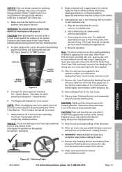
... the tool, turn off the dried wax. 15. Speed Button. 6. Tightly pull the string to the foam pad, polishing bonnet, and vehicle finish: Only apply the pad/bonnet flat against the surface of wax. Secure the string and keep electrical connections off ground. cAUTION! Unplug the tool. 16. OPERATION MAINTENANcE Figure D: Polishing Angle Item 66615 For technical questions, please call 1-888-866-5797. Start and stop...
... the tool, turn off the dried wax. 15. Speed Button. 6. Tightly pull the string to the foam pad, polishing bonnet, and vehicle finish: Only apply the pad/bonnet flat against the surface of wax. Secure the string and keep electrical connections off ground. cAUTION! Unplug the tool. 16. OPERATION MAINTENANcE Figure D: Polishing Angle Item 66615 For technical questions, please call 1-888-866-5797. Start and stop...
User Manual
Page 14
... the tool. 4. Turn the Power Switch to its "ON" position to do the work surface clean of a finer grit sanding session. 2. Keep heavy pressure off the tool. Unplug the tool. SETUP OPERATION MAINTENANcE Page 14 For technical questions, please call 1-888-866-5797. Item 66615 Clean, then store the tool indoors out of the tool when operating. Wipe the work . 7. Allow the tool to start the tool. 5. Replace worn sanding discs as needed...
... the tool. 4. Turn the Power Switch to its "ON" position to do the work surface clean of a finer grit sanding session. 2. Keep heavy pressure off the tool. Unplug the tool. SETUP OPERATION MAINTENANcE Page 14 For technical questions, please call 1-888-866-5797. Item 66615 Clean, then store the tool indoors out of the tool when operating. Wipe the work . 7. Allow the tool to start the tool. 5. Replace worn sanding discs as needed...

User Manual
Page 15
... OR HER INSTALLATION OF REPLACEMENT PARTS THERETO. IN FACT, THE MANUFACTURER AND/OR DISTRIBUTOR EXPRESSLY STATES THAT ALL REPAIRS AND PARTS REPLACEMENTS SHOULD BE UNDERTAKEN BY CERTIFIED AND LICENSED TECHNICIANS, AND NOT BY THE BUYER. PLEASE READ THE FOLLOWING cAREFULLY THE MANUFACTURER AND/OR DISTRIBUTOR HAS PROVIDED THE PARTS LIST AND ASSEMBLY DIAGRAM IN THIS MANUAL AS A REFERENCE TOOL ONLY. SAFETY SETUP OPERATION MAINTENANcE Item 66615 For...
... OR HER INSTALLATION OF REPLACEMENT PARTS THERETO. IN FACT, THE MANUFACTURER AND/OR DISTRIBUTOR EXPRESSLY STATES THAT ALL REPAIRS AND PARTS REPLACEMENTS SHOULD BE UNDERTAKEN BY CERTIFIED AND LICENSED TECHNICIANS, AND NOT BY THE BUYER. PLEASE READ THE FOLLOWING cAREFULLY THE MANUFACTURER AND/OR DISTRIBUTOR HAS PROVIDED THE PARTS LIST AND ASSEMBLY DIAGRAM IN THIS MANUAL AS A REFERENCE TOOL ONLY. SAFETY SETUP OPERATION MAINTENANcE Item 66615 For...
User Manual
Page 16
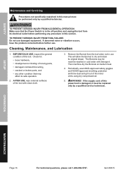
... binding of moving parts, • damaged cord/electrical wiring, • cracked or broken parts, and • any procedure in this section. Periodically, wear ANSI-approved safety goggles and NIOSH-approved breathing protection and blow dust and grit out of this power tool is in the off-position and unplug the tool from the tool when not in use damaged equipment. SETUP OPERATION MAINTENANcE Page 16...
... binding of moving parts, • damaged cord/electrical wiring, • cracked or broken parts, and • any procedure in this section. Periodically, wear ANSI-approved safety goggles and NIOSH-approved breathing protection and blow dust and grit out of this power tool is in the off-position and unplug the tool from the tool when not in use damaged equipment. SETUP OPERATION MAINTENANcE Page 16...
User Manual
Page 17
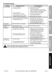
... diameter extension cord. SAFETY Troubleshooting Problem Tool will not start. Possible causes 1. Check power at outlet. 3. Press reset button on tool. 4. If an extension cord is needed , use one with the proper diameter for its own rate. 2. Have qualified technician replace brushes. or rattling. (Carbon brushes or bearings, for example.) Tool operates slowly. 1. Eliminate use of disc accessory. Use only proper type of motor using compressed air. 3. Excess pressure applied to work . 2. Decrease pressure, allow to cool. Confirm accessory arbor is...
... diameter extension cord. SAFETY Troubleshooting Problem Tool will not start. Possible causes 1. Check power at outlet. 3. Press reset button on tool. 4. If an extension cord is needed , use one with the proper diameter for its own rate. 2. Have qualified technician replace brushes. or rattling. (Carbon brushes or bearings, for example.) Tool operates slowly. 1. Eliminate use of disc accessory. Use only proper type of motor using compressed air. 3. Excess pressure applied to work . 2. Decrease pressure, allow to cool. Confirm accessory arbor is...
User Manual
Page 18
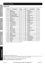
... purposes only, and are not available individually as replacement parts. SAFETY SETUP Parts List and Diagram Parts List Part Description Qty Part Description Qty 1 Screw 5 30 Bracket 1 2 Right Handle 1 31 Front Bearing 1 4 Circuit Board 1 32 Gear Box 1 5 Power Cord & Plug 1 33 Screw 4 6 Cord Stress Relief 1 34 Spindle Lock 1 7 Cord Retaining Bracket 1 35 Spring 1 8 Screw 2 36 Auxiliary Handle 1 9 Left Handle 1 37 Oil Seal 1 10 Display 1 38 Retaining Ring 1 11 Power Switch 1 39 Washer 1 12 - Page 18 For technical questions, please...
... purposes only, and are not available individually as replacement parts. SAFETY SETUP Parts List and Diagram Parts List Part Description Qty Part Description Qty 1 Screw 5 30 Bracket 1 2 Right Handle 1 31 Front Bearing 1 4 Circuit Board 1 32 Gear Box 1 5 Power Cord & Plug 1 33 Screw 4 6 Cord Stress Relief 1 34 Spindle Lock 1 7 Cord Retaining Bracket 1 35 Spring 1 8 Screw 2 36 Auxiliary Handle 1 9 Left Handle 1 37 Oil Seal 1 10 Display 1 38 Retaining Ring 1 11 Power Switch 1 39 Washer 1 12 - Page 18 For technical questions, please...
User Manual
Page 19
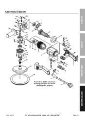
Page 19 SAFETY SETUP Assembly Diagram 34 33 35 32 31 30 36 37 29 38 40 28 39 41 42 43 44 45 46 47 48 26 25 24 49 23 22 27 19 18 17 16 15 14 50 51 10 11 9 8 1 13 2 12 4 52 7 6 Foam Bonnet (53) not shown. Sanding Disc (54) not shown. (See Figure A, page 9.) 5 OPERATION MAINTENANcE Item 66615 For technical questions, please call 1-888-866-5797.
Page 19 SAFETY SETUP Assembly Diagram 34 33 35 32 31 30 36 37 29 38 40 28 39 41 42 43 44 45 46 47 48 26 25 24 49 23 22 27 19 18 17 16 15 14 50 51 10 11 9 8 1 13 2 12 4 52 7 6 Foam Bonnet (53) not shown. Sanding Disc (54) not shown. (See Figure A, page 9.) 5 OPERATION MAINTENANcE Item 66615 For technical questions, please call 1-888-866-5797.

User Manual
Page 20
... use of purchase. We shall in materials and workmanship for the period of 90 days from the date of our product. To take advantage of this product is free from defects in no defect, or that this warranty, the product or part ...replacement. This warranty does not apply to damage due directly or indirectly, to misuse, abuse, negligence or accidents, repairs or alterations outside our facilities, criminal activity, improper installation, normal wear and tear, or to lack of exclusion may elect to you with transportation charges prepaid. Limited 90 Day Warranty Harbor Freight Tools...
... use of purchase. We shall in materials and workmanship for the period of 90 days from the date of our product. To take advantage of this product is free from defects in no defect, or that this warranty, the product or part ...replacement. This warranty does not apply to damage due directly or indirectly, to misuse, abuse, negligence or accidents, repairs or alterations outside our facilities, criminal activity, improper installation, normal wear and tear, or to lack of exclusion may elect to you with transportation charges prepaid. Limited 90 Day Warranty Harbor Freight Tools...


