

User Manual
Page 2
... result in minor or moderate injury. REMOVE ADJUSTING KEYS AND WRENCHES. DON'T USE IN DANGEROUS ENVIRONMENT. Keep work area. 6. MAKE WORKSHOP KID PROOF with padlocks, master switches, or by removing starter keys. 7. Don't force tool or attachment to personal injury. Indicates a hazardous situation which it on. 3. Form habit of Contents Safety 2 Specifications 5 Setup 6 Operation 8 Maintenance 10 Parts List and Diagram 14 Warranty 16 SAFETy SETUp OpERATION WARNING SyMBOLS AND DEFINITIONS This is...
... result in minor or moderate injury. REMOVE ADJUSTING KEYS AND WRENCHES. DON'T USE IN DANGEROUS ENVIRONMENT. Keep work area. 6. MAKE WORKSHOP KID PROOF with padlocks, master switches, or by removing starter keys. 7. Don't force tool or attachment to personal injury. Indicates a hazardous situation which it on. 3. Form habit of Contents Safety 2 Specifications 5 Setup 6 Operation 8 Maintenance 10 Parts List and Diagram 14 Warranty 16 SAFETy SETUp OpERATION WARNING SyMBOLS AND DEFINITIONS This is...

User Manual
Page 3
.... SETUp OpERATION MAINTENANCE Item 61613 For technical questions, please call 1-888-866-5797. SAFETy Table A: RECOMMENDED MINIMUM WIRE GAUGE FOR EXTENSION CORDS (120 VOLT) NAMEpLATE AMpERES (at all times. 14. When using your extension cord is unintentionally contacted. 19. The smaller the gauge number, the heavier the cord. 10. WEAR PROPER APPAREL. Consult the owner's manual for best and safest performance. TURN POWER OFF. Also use face or dust mask if cutting operation...
.... SETUp OpERATION MAINTENANCE Item 61613 For technical questions, please call 1-888-866-5797. SAFETy Table A: RECOMMENDED MINIMUM WIRE GAUGE FOR EXTENSION CORDS (120 VOLT) NAMEpLATE AMpERES (at all times. 14. When using your extension cord is unintentionally contacted. 19. The smaller the gauge number, the heavier the cord. 10. WEAR PROPER APPAREL. Consult the owner's manual for best and safest performance. TURN POWER OFF. Also use face or dust mask if cutting operation...

User Manual
Page 4
... only one blade is specifically designed for 2-prong plug.) Grinder Tool Safety Warnings For your Own Safety Read Instruction Manual Before Operating Grinder 1. Double insulated tools may be NIOSH-approved for wet grinding. 5. Do not use . 6. Mount securely before use for the specific hazards in a risk of grinding. 16. Inspect wheel before moving saw chain. 8. Do not overtighten wheel nut. 10. Adjust distance between wheel and work before use only identical replacement parts. 18. Only use a power tool while...
... only one blade is specifically designed for 2-prong plug.) Grinder Tool Safety Warnings For your Own Safety Read Instruction Manual Before Operating Grinder 1. Double insulated tools may be NIOSH-approved for wet grinding. 5. Do not use . 6. Mount securely before use for the specific hazards in a risk of grinding. 16. Inspect wheel before moving saw chain. 8. Do not overtighten wheel nut. 10. Adjust distance between wheel and work before use only identical replacement parts. 18. Only use a power tool while...

User Manual
Page 5
...hands after handling. (California Health & Safety Code § 25249.5, et seq.) 26. To reduce the risk of it). Do not smoke during use . Nicotine reduces the blood supply to UL STD No. 987 OpERATION MAINTENANCE Item 61613 For technical questions, please call 1-888-866-5797. To reduce vibration, maintain the tool as those dust... injury: 1. Specifications Electrical Rating Motor No Load Speed Saw Chain Pitch Arbor Size Vise Capacity Max. Use tools with approved safety equipment, such as explained in a well ventilated area, and work in this instruction manual cannot cover all...
...hands after handling. (California Health & Safety Code § 25249.5, et seq.) 26. To reduce the risk of it). Do not smoke during use . Nicotine reduces the blood supply to UL STD No. 987 OpERATION MAINTENANCE Item 61613 For technical questions, please call 1-888-866-5797. To reduce vibration, maintain the tool as those dust... injury: 1. Specifications Electrical Rating Motor No Load Speed Saw Chain Pitch Arbor Size Vise Capacity Max. Use tools with approved safety equipment, such as explained in a well ventilated area, and work in this instruction manual cannot cover all...

User Manual
Page 6
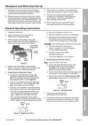
... Base with the Angle Adjustment Knob. 2. Vise Assembly Figure B Bolt Angle Adjustment Knob Clamp Lock Nut Vise Cable Clamp plate Figure C OpERATION MAINTENANCE Page 6 For technical questions, please call 1-888-866-5797. Item 61613 Mounting Note: The Sharpener must be mounted on page 5, at the beginning of the tool off and unplug the tool from the Vise Cable 3. Slide the bolt on the bottom of mounting holes. 3. Secure from underneath with the hardware. Remove...
... Base with the Angle Adjustment Knob. 2. Vise Assembly Figure B Bolt Angle Adjustment Knob Clamp Lock Nut Vise Cable Clamp plate Figure C OpERATION MAINTENANCE Page 6 For technical questions, please call 1-888-866-5797. Item 61613 Mounting Note: The Sharpener must be mounted on page 5, at the beginning of the tool off and unplug the tool from the Vise Cable 3. Slide the bolt on the bottom of mounting holes. 3. Secure from underneath with the hardware. Remove...

User Manual
Page 7
Functions Vise Handle Depth Adjustment Knob Depth Adjustment Lock Nut SAFETy SETUp OpERATION Handle Vise Cable power Switch Chain Stop Adjustment Knob Depth Adjustment plate Depth Adjustment Stop Chain Stop Clamp plate Vise Safety Guard Chain Stop Lock Nut Item 61613 Chain Roller Knob Angle Adjustment Knob Chain Roller Knob For technical questions, please call 1-888-866-5797. Page 7 MAINTENANCE
Functions Vise Handle Depth Adjustment Knob Depth Adjustment Lock Nut SAFETy SETUp OpERATION Handle Vise Cable power Switch Chain Stop Adjustment Knob Depth Adjustment plate Depth Adjustment Stop Chain Stop Clamp plate Vise Safety Guard Chain Stop Lock Nut Item 61613 Chain Roller Knob Angle Adjustment Knob Chain Roller Knob For technical questions, please call 1-888-866-5797. Page 7 MAINTENANCE
User Manual
Page 8
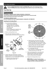
... Flange Grinding Wheel Spindle Inner Flange Arbor Grinding Wheel Cover Figure D 4. Tool Set Up TO pREVENT SERIOUS INJURy FROM ACCIDENTAL OpERATION: Turn the power Switch of the tool off and unplug the tool from its electrical outlet before mounting. Suspend wheel using a dowel or finger through the arbor hole. Replace the Grinding Wheel Cover. Closely inspect the wheel before performing any procedure in diameter. • fitted with a light non-metallic object...
... Flange Grinding Wheel Spindle Inner Flange Arbor Grinding Wheel Cover Figure D 4. Tool Set Up TO pREVENT SERIOUS INJURy FROM ACCIDENTAL OpERATION: Turn the power Switch of the tool off and unplug the tool from its electrical outlet before mounting. Suspend wheel using a dowel or finger through the arbor hole. Replace the Grinding Wheel Cover. Closely inspect the wheel before performing any procedure in diameter. • fitted with a light non-metallic object...
User Manual
Page 9
... on the Miter Gauge, then tighten the Angle Adjustment Knob. Turn the Sharpener on the spokes of the Gullet. Turn off before reinstalling it on the Handle to keep saw . 8. b. Sharpening the righthand cutters: beginning at i. OpERATION MAINTENANCE Figure F: Right-hand Cutter Item 61613 For technical questions, please call 1-888-866-5797. Page 9 The power cord must not allow free movement while working . 4. Wear heavy-duty gloves when handling the saw chain does...
... on the Miter Gauge, then tighten the Angle Adjustment Knob. Turn the Sharpener on the spokes of the Gullet. Turn off before reinstalling it on the Handle to keep saw . 8. b. Sharpening the righthand cutters: beginning at i. OpERATION MAINTENANCE Figure F: Right-hand Cutter Item 61613 For technical questions, please call 1-888-866-5797. Page 9 The power cord must not allow free movement while working . 4. Wear heavy-duty gloves when handling the saw chain does...
User Manual
Page 10
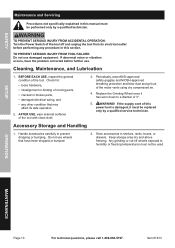
... ACCIDENTAL OpERATION: Turn the power Switch of moving parts, • cracked or broken parts, • damaged electrical wiring, and • any procedure in shelves, racks, boxes, or drawers. Periodically, wear ANSI-approved safety goggles and NIOSH-approved breathing protection and blow dust and grit out of 3". 5. Do not use damaged equipment. Item 61613 If the supply cord of this section. Accessory Storage and Handling 1. If...
... ACCIDENTAL OpERATION: Turn the power Switch of moving parts, • cracked or broken parts, • damaged electrical wiring, and • any procedure in shelves, racks, boxes, or drawers. Periodically, wear ANSI-approved safety goggles and NIOSH-approved breathing protection and blow dust and grit out of 3". 5. Do not use damaged equipment. Item 61613 If the supply cord of this section. Accessory Storage and Handling 1. If...

User Manual
Page 11
... cord. Eliminate use of motor using compressed air. 4. Disconnect power supply before service. No power at outlet. Tool's thermal reset breaker tripped (if equipped). 4. Carbon brushes worn or damaged. 1. Internal damage or wear. (Carbon brushes or bearings, for example.) Extension cord too long or wire size too small. Blocked motor housing vents. 4. Check power at outlet. Have technician service tool. Keep cutting accessories sharp. See Table A on page 3. 1. Page 11 SAFETy Troubleshooting problem possible Causes Tool will not start...
... cord. Eliminate use of motor using compressed air. 4. Disconnect power supply before service. No power at outlet. Tool's thermal reset breaker tripped (if equipped). 4. Carbon brushes worn or damaged. 1. Internal damage or wear. (Carbon brushes or bearings, for example.) Extension cord too long or wire size too small. Blocked motor housing vents. 4. Check power at outlet. Have technician service tool. Keep cutting accessories sharp. See Table A on page 3. 1. Page 11 SAFETy Troubleshooting problem possible Causes Tool will not start...

User Manual
Page 12
... THE MANUFACTURER AND/OR DISTRIBUTOR HAS PROVIDED THE PARTS LIST AND ASSEMBLY DIAGRAM IN THIS MANUAL AS A REFERENCE TOOL ONLY. THE BUYER ASSUMES ALL RISK AND LIABILITY ARISING OUT OF HIS OR HER REPAIRS TO THE ORIGINAL PRODUCT OR REPLACEMENT PARTS THERETO, OR ARISING OUT OF HIS OR HER INSTALLATION OF REPLACEMENT PARTS THERETO. Item 61613 SAFETy SETUp OpERATION MAINTENANCE Page 12 For technical questions, please call...
... THE MANUFACTURER AND/OR DISTRIBUTOR HAS PROVIDED THE PARTS LIST AND ASSEMBLY DIAGRAM IN THIS MANUAL AS A REFERENCE TOOL ONLY. THE BUYER ASSUMES ALL RISK AND LIABILITY ARISING OUT OF HIS OR HER REPAIRS TO THE ORIGINAL PRODUCT OR REPLACEMENT PARTS THERETO, OR ARISING OUT OF HIS OR HER INSTALLATION OF REPLACEMENT PARTS THERETO. Item 61613 SAFETy SETUp OpERATION MAINTENANCE Page 12 For technical questions, please call...

User Manual
Page 13
Page 13 Record product's Serial Number Here: Note: If product has no serial number, record month and year of purchase instead. Note: Some parts are listed and shown for illustration purposes only, and are not available individually as replacement parts. SAFETy SETUp OpERATION MAINTENANCE Item 61613 For technical questions, please call 1-888-866-5797.
Page 13 Record product's Serial Number Here: Note: If product has no serial number, record month and year of purchase instead. Note: Some parts are listed and shown for illustration purposes only, and are not available individually as replacement parts. SAFETy SETUp OpERATION MAINTENANCE Item 61613 For technical questions, please call 1-888-866-5797.
User Manual
Page 14
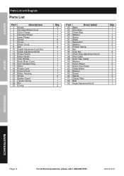
Item 61613 SAFETy parts List and Diagram parts List part Description 1 Screw 2 Grinding Wheel Cover 3 Outer Flange 4 Grinding Wheel 5 Inner Flange 6 Screw 7 Screw 8 Motor Cover 9 Nut 10 Depth Adjustment Lock Nut 11 Depth Adjustment Knob 12 Power Switch 13 Main Handle 14 Vise Handle 15 Back Motor Cover 16 Anti Vibration Ring 17 Motor 18 Power Cord 19 Circuit Panel 20 Motor Housing 21 Screw 22 Safety Guard 23 Torsion Spring 24 Pin 25 Circlip Qty. 3 1 1 1 1 11 2 1 2 1 1 1 1 1 1 1 1 1 1 1 2 1 1 1 2 part Description 26 Base 27 Vise Base 28 Chain Stop 29 Washer...
Item 61613 SAFETy parts List and Diagram parts List part Description 1 Screw 2 Grinding Wheel Cover 3 Outer Flange 4 Grinding Wheel 5 Inner Flange 6 Screw 7 Screw 8 Motor Cover 9 Nut 10 Depth Adjustment Lock Nut 11 Depth Adjustment Knob 12 Power Switch 13 Main Handle 14 Vise Handle 15 Back Motor Cover 16 Anti Vibration Ring 17 Motor 18 Power Cord 19 Circuit Panel 20 Motor Housing 21 Screw 22 Safety Guard 23 Torsion Spring 24 Pin 25 Circlip Qty. 3 1 1 1 1 11 2 1 2 1 1 1 1 1 1 1 1 1 1 1 2 1 1 1 2 part Description 26 Base 27 Vise Base 28 Chain Stop 29 Washer...

User Manual
Page 15
Assembly Diagram SAFETy SETUp OpERATION MAINTENANCE Item 61613 For technical questions, please call 1-888-866-5797. Page 15
Assembly Diagram SAFETy SETUp OpERATION MAINTENANCE Item 61613 For technical questions, please call 1-888-866-5797. Page 15

User Manual
Page 16
... MERCHANTABILITY AND FITNESS. We will either repair or replace the product at our expense, but if we determine there is free from defects in no defect, or that this warranty, the product or part must accompany the merchandise. Limited 90 Day Warranty Harbor Freight Tools Co. This warranty does not apply to damage due directly or indirectly, to misuse, abuse, negligence...
... MERCHANTABILITY AND FITNESS. We will either repair or replace the product at our expense, but if we determine there is free from defects in no defect, or that this warranty, the product or part must accompany the merchandise. Limited 90 Day Warranty Harbor Freight Tools Co. This warranty does not apply to damage due directly or indirectly, to misuse, abuse, negligence...


