User Manual
Page 1
... is subject to the unit for future reference. AUTOMOBILE, SPACE HEATER, WATER HEATER,ETC.) INSURE THAT THE ENCLOSED AREA IS PROPERLY VENTILATED. Installation & Operation Manual Air Handler 13 SEER 2 3 4 5 Ton WARNING WHEN THIS APPLIANCE IS INSTALLED IN AN ENCLOSED AREA, SUCH AS A GARAGE OR UTILITY ROOM, WITH ANY CARBON MONOXIDE PRODUCING DEVICES...
... is subject to the unit for future reference. AUTOMOBILE, SPACE HEATER, WATER HEATER,ETC.) INSURE THAT THE ENCLOSED AREA IS PROPERLY VENTILATED. Installation & Operation Manual Air Handler 13 SEER 2 3 4 5 Ton WARNING WHEN THIS APPLIANCE IS INSTALLED IN AN ENCLOSED AREA, SUCH AS A GARAGE OR UTILITY ROOM, WITH ANY CARBON MONOXIDE PRODUCING DEVICES...
User Manual
Page 7
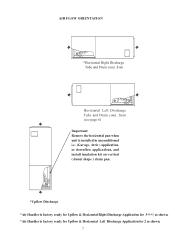
front Horizontal Left Discharge Tube and Drain conn. front (see page 6) Important: Remove the horizontal pan when unit is installed in unconditioned i.e. (Garage, Attic ) application, or downflow applications, and install insulation kit on vertical ( donut shape ) drain pan. *Upflow Discharge *Air Handler is factory ready for Upflow & Horizontal Right Discharge Application for 3*4*5 as shown. *Air Handler is factory ready for Upflow & Horizontal Left Discharge Application for 2 as shown. 7 AIR FLOW ORIENTATION *Horizontal Right Discharge Tube and Drain conn.
front Horizontal Left Discharge Tube and Drain conn. front (see page 6) Important: Remove the horizontal pan when unit is installed in unconditioned i.e. (Garage, Attic ) application, or downflow applications, and install insulation kit on vertical ( donut shape ) drain pan. *Upflow Discharge *Air Handler is factory ready for Upflow & Horizontal Right Discharge Application for 3*4*5 as shown. *Air Handler is factory ready for Upflow & Horizontal Left Discharge Application for 2 as shown. 7 AIR FLOW ORIENTATION *Horizontal Right Discharge Tube and Drain conn.
User Manual
Page 9
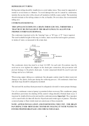
... a removal pump or float switch must exceed the total negative pressure, in the return duct. REFRIGERANT TUBING Refrigerant tubing should be installed as to the air handler. A "P " trap is required. NOTE: AFTER INSTALLATION AND POSITIONING THE UNIT , THE DRAIN PAN BEING USED SHOULD BE TESTED BY FILLING IT WITH WATER TO ENSURE...
... a removal pump or float switch must exceed the total negative pressure, in the return duct. REFRIGERANT TUBING Refrigerant tubing should be installed as to the air handler. A "P " trap is required. NOTE: AFTER INSTALLATION AND POSITIONING THE UNIT , THE DRAIN PAN BEING USED SHOULD BE TESTED BY FILLING IT WITH WATER TO ENSURE...
User Manual
Page 10
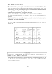
...when required by code. Model No. 2 Ton 3 Ton 4 Ton 5 Ton 5 Ton -E Min. The ampacity and overcurrent protection shown above is recommended for "HB" air handlers installed without a heat kit. 10 The wiring diagram included in the optional heat kit must be installed within sight of copper connections are recommended inside... of the unit. Max. ELECTRICAL CONNECTIONS The required electrical power supply information is located on the series and rating plate on the air handler. Copper wire is only for all electrical connections. When an optional heat kit is installed refer to the...
...when required by code. Model No. 2 Ton 3 Ton 4 Ton 5 Ton 5 Ton -E Min. The ampacity and overcurrent protection shown above is recommended for "HB" air handlers installed without a heat kit. 10 The wiring diagram included in the optional heat kit must be installed within sight of copper connections are recommended inside... of the unit. Max. ELECTRICAL CONNECTIONS The required electrical power supply information is located on the series and rating plate on the air handler. Copper wire is only for all electrical connections. When an optional heat kit is installed refer to the...


